The natural step after the CCNA is the CCNP, at least for most people. However, as you climb the networking ladder, resources get scarcer. This is completely normal: if few people have a certification, even fewer will write about it. You will learn CCNP most by practicing, but you need to start with the right foot. Of course, practice means lab, and what is the best way to starting with the right foot, if not with the best CCNP lab setup? In this article, we will explain how to connect routers and switches to maximize the results in terms of learning.
Don’t have the CCNA yet? Then check out our complete CCNA guide, it is online and free!
The goals for our CCNP lab setup
You get CCNP certified by passing three exams: one about switching, one about routing, and another about troubleshooting. So, we designed our CCNP lab setup to allow you to get the most out of each area. We kept in mind these items when creating this setup:
- Maximize adjacencies: if each router can see the others in multiple ways we can create complex logical topologies
- Keep hardware to a bare minimum: for the ones of you that want to buy real hardware, we know it can be expensive, so we didn’t add any fancy stuff
- Must be replicable in GNS3 – that’s pretty self-explanatory
- Allows the creation of all labs in CCNP
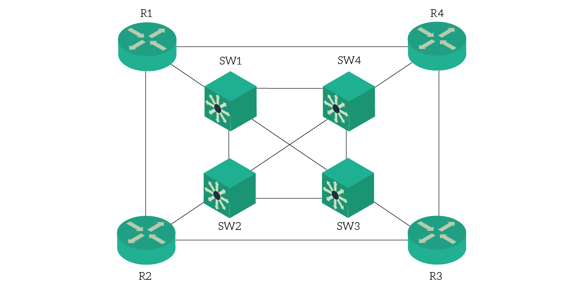
With these goals in mind, we took four routers and four switches. Then, we connected them in a very special way.
The best CCNP lab setup
The topology
Our topology is simple is connected to the two other routers and to a multi-layer switch. The switches are connected together in a full-mesh topology. The result is something like this.

This might seem simple, and it is. However, it has a lot of potential in many different areas. In the following paragraphs, we will see how to use it for BGP (eBGP and iBGP), advanced routing, and so on.
Multiply the number of routers
At this point, many people think “Ok, I can get a great lab with 8 devices, but I won’t replicate a real scenario”. Well, think again, because while we have 4 physical routers, we can easily turn them to 8, 12, or even 16. In fact, our CCNP lab setup leverages VRF in some specific circumstances.
For the ones of you new to it, VRF is a routing virtualization and abstraction technology. You take a router and associate each interface to a given VRF name. Then, all interfaces with the same VRF name will be part of the same virtual router. Each virtual router has its own routing table and is independent of the other or from the physical router itself.
Of course, VRF alone is not enough. But the concept we are going to use to increase separation is even simpler: VLANs. VRF is a Layer 3 concept, VLAN is a Layer 2 segregation concept, so they work well together. In fact, you can create sub-interfaces on the routers’ links, and then associate each of them to a different VLAN. Boom, we have endless routing possibilities.
What about switching?
When doing the switching, you don’t have the concept of VRF. However, you don’t need that. CCNP switching topics can be replicated in a lab with very few switches. That’s why our CCNP lab setup uses only four of them. To enhance your possibilities, however, we recommend using multilayer switches.
CCNP lab setup use cases
In this part of the article, we will show what you can do with such a lab. Specifically, we will explain how to divide the lab into different VRFs and VLANs to create a logical topology that best meets a given scenario.
The BGP lab
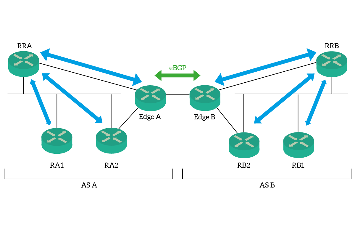
In this CCNP lab setup, you can easily try all the BGP concepts in a single-homed connection between two Autonomous Systems. In fact, you can try eBGP, iBGP, and Route Reflectors in action. Here’s what the topology looks like.

As you can see, we have two systems composed of four routers each which are exactly specular. To accomplish this in our lab, we create the entire AS A on R1 and R2 and the AS B on R3 and R4. As a result, the link connecting EdgeA and EdgeB is nothing more than the link between R2 and R3. We run the route reflector of A (RRA) on R1, and then create RA1 in a VRF on R1, and RA2 in a VRF on R2. To connect them, we create a dedicated VLAN which we make available to RRA as well (the other virtual router on R1).
Of course, we repeat the process on the other Autonomous System and we are ready to get BGP rocking. This is probably one of the best things you can do with this CCNP lab setup.
The Multiple Spanning Tree LAN
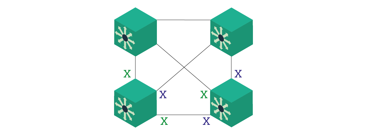
Multiple Spanning Tree (MST) is an awesome protocol that can cut down the resources used by STP. It’s a key item for the switching part of the CCNP, and you simply create all the labs you want with four switches. In fact, you don’t need to play a lot with VLANs or VRFs for this lab, the topology is ready.

Multiple Spanning Tree is an advanced version of STP. It groups VLANs into STP instances, and then run the STP algorithm on a per-instance basis, rather than on a per-VLAN basis. Fewer algorithms running means fewer resources, which is always great. As in the picture, a great lab you could do is create a lot of VLANs, then associate them to the blue and green instance. This way, you can play and block some links for an instance or for some other. As in this example, you should create two MST instances, the blue, and the green. Each instance will block some links instead of some others.
Bridging OSPF Area 0 in a lab
If you have the rudiments of OSPF, you know that it groups routers in areas. All areas must be connected to Area 0, however, otherwise, we have problems. CCNP teaches you a way to make it work even if the Area 0 is split into two parts. Remember that this is a temporary solution when migrating networks, and should not be used in production. Here’s what our CCNP lab setup looks like.

Creating this is simple, as you don’t need VRF. In fact, you can use the external links that connect directly routers to create this chain. Then, you can shut down the link between R1 and R4. Done, you can now practice in bridging/tunneling Area 0.
Conclusion
Now that we understand the possibility of this lab, you can learn CCNP and practice it with this powerful tool. And, if you don’t want to bu the hardware, you should really check our GNS3 tutorial to have it running for free on your laptop. With this lab, you are going to reach the CCNP faster: don’t think about how to create a lab, think about how to solve it, and save time!
What do you think about this lab? What technologies will you try in it? Would you like to improve something? Just let me know in the comments!
