A data center hosts hundreds or even thousands of servers. In fact, the goal of a data center is packing all the servers in the same place. However, lots of servers means a lot of required connections and lots of cabling. If you don’t have a clear design, you will end up with horrible spaghetti cabling. To avoid that, this article explains some common practices you should know during the design of data center cabling. Besides that, you will learn some tips from the network battleground that you won’t find in official courses.
Be creative: you can apply what we explain in this article to any network setup, not just in the data center. For example, you can apply it to a campus or to a branch office.
Data Center Cabling explained
What is a Data Center, in the end?
We can find a lot of fancy definitions for data center. However, today our only job is to work on cabling. From this point of view, a data center is just a bunch of server racks within the same facility. For smaller installations, all racks may be in a single room, and you may have 5 to 20 racks. If you start to grow from these numbers, racks will be scattered across several rooms. You might even have them on multiple floors, for big installations.
A data center is just a bunch of server racks within the same facility.
For this article, we will not see all other characteristics of a data center, like virtualization or multi tenancy. Instead, we will focus on the physical infrastructure: the cabling. This infrastructure must be prepared in such a way that two devices that needs to connect with each other can do that. We can do this with two types of cabling, as we will see in the next section.
Patches & Structured Cabling
When it comes to data center cabling, you have two different categories of cabling: patches and structured cabling. Both can be of any technology, typically copper or fiber. However, their role is clearly different.
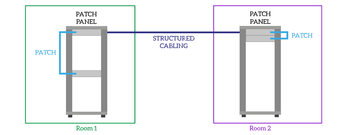
A patch is a cable that connects two devices on the same rack. Patches are generally up to 5 meters long, and the smallest ones can be just as 30cm. Even if a 5m patch is long enough to connect two close racks, you should never, never do that. If you do, your cabling will be a mess sooner or later (probably sooner). A patch can be the classic ethernet cable you use at home or a short fiber connection.
Instead, structured cabling is what runs behind the scenes. The role of this data center cabling category is connecting different racks together. However, they are not just normal cables like the ethernet cable we mentioned before. Structured cabling runs between a rack and another, and terminates inside a passive device: the patch panel. This device is just a bunch of female connectors (fiber or copper, depending on the technology), stacked together in the same Rack Unit. You can plug a patch inside these connectors, and the patch will connect to the structured cabling. Then, the structured cabling behind the patch panel runs to the other rack. On the other side, we have another patch panel where we can plug another patch. This way, we can connect two devices in two separate racks.

The whole data center cabling is a combination of patches and structured cabling.
Designing Structured Cabling
When working with patches, you can connect them when you install the devices. Instead, you need to plan all structured cabling when designing the data center. You can’t easily run a cable from behind a patch panel once you have installed all the devices you need. Thus, you need to prepare all the structured cabling when building the data center.
At this point, we need to answer a question: how can we prepare structured cabling to connect different racks efficiently? A patch panel in a rack connects to a patch panel in another rack. The result is that you use 1 Rack Unit in your rack for each other rack you want to connect to. With hundreds if not thousands of racks, achieving a full mesh of structured cabling is impossible. Even if it was possible, it would have been extremely costly. We need to find another solution.
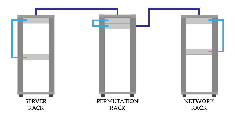
Think about it, in the end, no server needs a direct cable to another server somewhere else in the data center. Instead, all servers connect to network devices. Network devices instead are likely to connect with each other. A common approach is to prepare the structured cabling from each server rack only to network racks, that will host only network devices. However, since you can have many network racks as well, you can use a permutation rack. This rack hasonly patch panels, and you connect all server racks and network racks to the permutation one with structured cabling. Then, you add patches in it. This allows you to dynamically create a physical connection between any server and any network device using patches.

TOR Switches
Using one or two permutation racks is great for small and mid-sized data centers. For large ones, this starts to fall apart. Racks can have up to 46 Rack Unit, this means you can connect up to 23 racks together if you do not use any cable organizer (and you want to use them). Furthermore, servers may have copper connections that can run up to 100 meters, but you may need to cover greater distances.
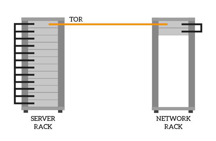
In large data centers, you use Top Of the Rack (TOR) switches. Basically, you equip every single server rack with a switch, or possibly a stack/pair of them. You install this switch on the highest rack units, where the patch panel would have been, this is why Top of the Rack. Then, using a fiber patch panel or a direct link, you connect the switch to the permutation rack. Now the structured cabling doesn’t need to run a whole bunch of ethernet cables, but just a pair of fiber links. On the other side, in the permutation rack, you can have a single fiber patch panel dispatching connections to multiple TOR switches in different racks. Because of that, you may even skip the permutation rack and install the patch panel where the distribution switch for the TORs is.

Take care about the connectors
When creating a new data center, you may want to use all the same connectors data center-wise. For copper, we have no problem, as it only uses RJ45, but with the fiber, it is a whole different game. The current fiber connector is LC, and you should implement just this one in new setups. However, you might work with older data center cabling in existing data centers. In such cases, patch panels often have SC fiber connectors, or even ST (much older). You need to consider all of that when you need to make some activities on existing data centers, specifically if you never worked in such a data center. If you need to change some patches, check if the previous patch was single-mode or multi-mode.
However, don’t worry. All connector pairs you can think of already exist. You can find ST-LC patches, SC-SC patches, and so on.
Reconstructing the path
From what we explained above, your connection between two devices can traverse multiple racks and patch panels. You want to have a way to identify that, instead of checking where the cable goes manually. First, you should label each patch with two labels: one on each side. An approach is put on the label the name of the device on the other side, but this can quickly fall apart if you move the cables. A more standard approach is to label each cable with a Unique ID, like a progressive number. Of course both sides, the ID must be the same.
Now that you have a way to identify patches, we need a way to identify structured cabling. First, we need a way to identify patch panels. We do that with the unique position in the data center. An example label can be 1NT01-46. From it, we can extract the following information.
| Code | Stands For | Description |
|---|---|---|
| 1 | 1 | Floor in the facility where this patch panel is. |
| NT | Network | Room within the floor where the patch panel is located. |
| 01 | 1 | Rack within the room where the patch panel is. |
| 46 | 46 | Rack unit within the rack where the patch panel is. |
Of course, NT stands for Network because we decided that. You should define your own naming convention and keep it consistent, to ensure a unique ID of patch panels.
Then, identifying the structured cabling is simple. You just name your patch panel, followed by a slash, followed by the name of the patch panel on the other side. For example, the cabling that connects a rack in the server room to a rack in the network room will look like 1SR23-46/1NT01-14. For more information, refer to the ANSI standard ANSI/TIA-606-B.
Cables must go up
In the past, cabling between racks was laid below the pavement. This reduced the total length of structured cabling, thus saving costs. However, it made cabling a real pain to maintain and expand. Once you have a rack installed with a lot of devices in it, it starts to get hard-working inside the floor. Because of that, the current best practice is to run cables above the racks, preparing open conduits that run near the ceiling. Each rack has a conduit raising to the ceiling and joining the main conduit.
If you prepare your data center in this way, you will be able to scale data center cabling with ease, including structured cabling.
Consider power availability
While not strictly related to cabling, power is another thing you want to consider when designing a data center or when making activities on an existing one. Identify how many power lines you have, and if some of them are protected by a UPS. A common approach is to have two power lines, both protected by a UPS. To that, you can add a third power line that fetches power from the other two for single-PSU devices. You need to size electrical cabling and power generation to power all devices without any issue, but it is a whole different game we cannot cover today.
Last, but extremely important, check the power outlets! You may have PDU outlets, EU outlets, Schuko outlets, French outlets, and so on, depending on where your data center is in the world. A common approach is preferring PDU, which is standard and not country-specific, but existing data centers may have a different condition. If you fly oversea to perform an activity on a data center, don’t forget to ask which kind of outlets they have!
Wrapping it up
This article gave a quick introduction to data center cabling. You are now ready to understand how the connections in a data center work, even if you never stepped in any data center. You are ready to perform your activities, without the risk of being unable to power your switch because of a wrong plug.
At this point, you may want to consider other parts of the data center. The next steps would be to dive deeper into power, define the HVAC and airflow, and so on. Of course, designing a data center is a complex process, and in a single article, we cannot cover even a single component like the cabling. What do you think about this approach to cabling? What do you consider when designing a data center? Let me know in the comments!
