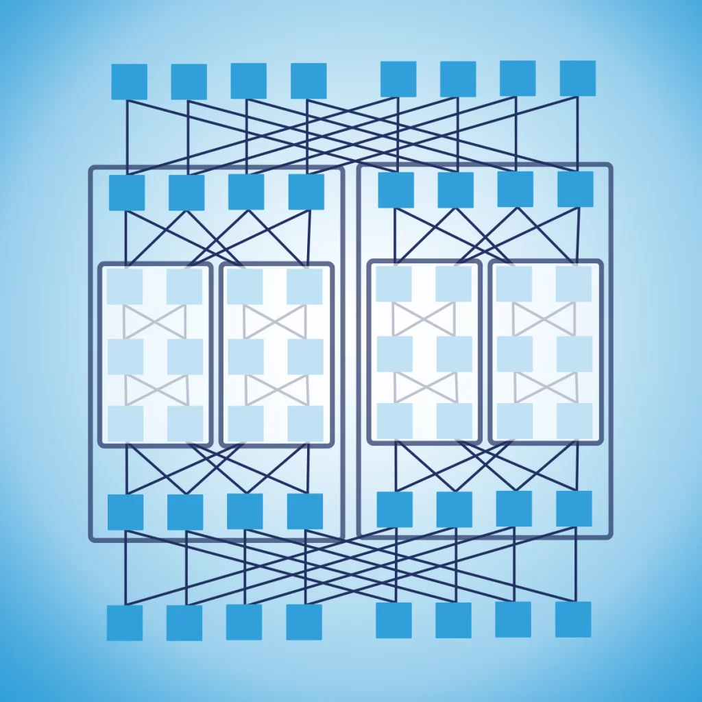
Welcome to the datacenter network design course! By completing this course, will be able to design a large datacenter that spans multiple locations and serves tens of thousands of servers. Here is how you can get the most out of this course and ensure your success.
A better version of this course is available for FREE via email. Get it here.
If you have questions throughout the course, reach out to me on LinkedIn, and I can help you out and consider expanding the course to make it clearer. To succeed, you need to have some basic networking knowledge, as we won’t spend much time explaining IP addresses or routing protocols. If you want to learn about that first, then take the Free CCNA Course on accelerates.it.
Take notes as you read through the chapters. I suggest doing it on paper, as research suggests it will stick in your memory more effectively, but do what works for you. Stick with it, enjoy, and follow the course until the end for a bonus (the bonus is only for people taking the course via email).
Here’s what to expect
In this course, we will cover everything you need to know to design a datacenter. To help you navigate this journey, this course has four sections that we will work on sequentially.
First, we start with the fabric view of the network. This section provides all the building blocks and terminology you need to understand datacenter network design. We will focus on the purpose of a datacenter network, what to consider as inputs or “starting points” for designing it. In this section, you will find these chapters:
- What does a datacenter network do?
- The building blocks
- Key Inputs
- Constraints
- The Network Fabric
We then move the data plane. This is the core of your network, and the main bulk of the guide. Here, we will focus on how to interconnect devices together to provide the right bandwidth, redundancy, and scalability to meet your requirements. We will explore different topologies, design patterns, and datacenter functionalities of the network. Here are the chapters in this section:
- L3 traffic only
- Focus on the underlay
- Core-Distribution-Access
- Subscription rate
- Equal Cost Multipath (ECMP)
- Spine-and-leaf in principle
- Spine-and-leaf connections
- Scaling spine-and-leaf
- 3-stage Clos topology
- Parameters for a Clos topology
- Designing a Clos network
- Multistage Clos network
- Network “bricks”
- Tiered datacenter design with bricks
- Fault scenarios
Once the data plane is in place, we will move to the control plane. In this section we will see how devices communicate with each other to have knowledge about the network and understand where to send traffic. This is the section where we discuss routing protocols and addressing space. We will cover these chapters:
- Natural boundaries in the network
- Standardization and summarization
- Routing information that matters – about servers
- BGP Architecture
- IGP architecture, ISIS
- Firewalls at the edge
We close with the management plane. Here, we will see how we can manage thousands of devices at scale, and how we can regularly deploy changes to those devices, enabling new functionalities quickly at datacenter scale and rolling out security patches. We will do it through these chapters:
- Out-of-band management
- Active and passive monitoring
- Shifting traffic
- Deployment best practices
Stick to the end, because you will get a bonus once the course is finished!
Fabric View of the Network
What does a datacenter network do?
A datacenter is a large warehouse full of servers, computers designed to run applications like websites, online games, social media, and more. We call those computers “servers” because they “serve” requests from clients when asked. Clients, on the other hand, are devices individuals use: smartphones, laptops, but also connected cars or smart-home devices.
Client-server communication is paramount: without it, the server has no reason to exist. Plus, server-to-server communication is also important, as modern applications are complex and require interactions of different components running on different servers.
A datacenter network is “that thing” that enables servers to communicate with each other and provides a path for communication outside of the datacenter with clients. We consider the network an infrastructure component. It is not something that customers want or seek, but it is something we need for customers to use what they want: applications and servers.
To best serve applications, the datacenter network needs to be resilient and correctly sized. Resilient means it provides stable connectivity, and even the failure of some physical components does not hinder the connection. Correctly sized means that we can provide the right amount of bandwidth for each communication flow, so that we do not block or congest server-to-server or client-to-server traffic.
The building blocks of datacenter network design
Our datacenter will host servers, and we want to optimize how they are installed and connected. All datacenters tend to use the same “building blocks” and combine them in slightly different ways.
The first component is the server; it is a computer that runs applications. In modern datacenters, this is virtualized: the same physical server can host multiple virtual machines, each acting as an individual server, logically separated from the others but sharing the same physical resources.
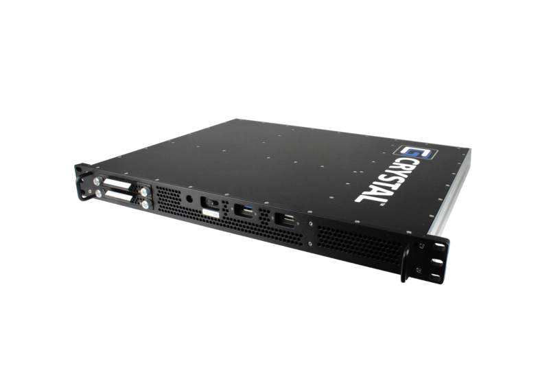
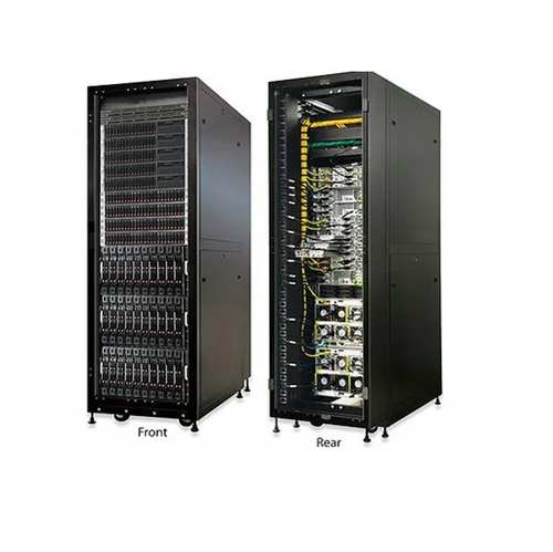
We install multiple servers into a rack. This is a standard-sized cabinet where we can stack servers one on top of the other. All racks are the same size, which means we can easily create rows of racks in a room inside the datacenter (DC). In a rack, you will find servers, but also other components: cables, switches, patch panels, power-related components. In this guide, we will focus on network design, but “rack design” is also an important component when designing a datacenter.
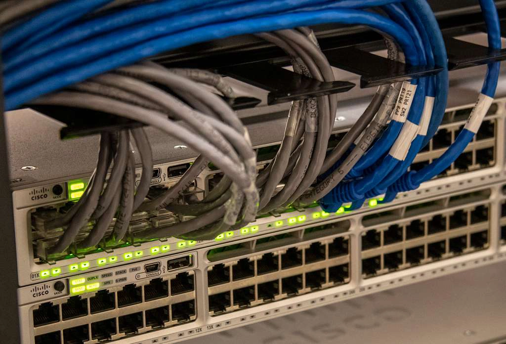
A switch is a network device that provides connectivity to other devices. It has many ports and connects multiple servers or other switches. We will use multiple switches to create our datacenter network architecture. If you are curios, you can see switches by popular vendors like Juniper or Cisco.
When we have a rack that mainly contains servers, we call it a compute rack. Instead, when we have a rack made only of network devices (like switches), we call it a network rack. A network rack provides the hardware components needed for compute racks and other network racks to communicate.
In each compute rack, we typically have two top-of-rack switches, or TORs. These are switches installed at the very top of the rack, above all the servers. They connect all the servers and provide connectivity to a network rack, which will relay connectivity to other compute racks and network racks in turn.
Key Inputs for datacenter network design
Designing a datacenter network is simply defining which building blocks to use, and how to configure them. To make those decisions, we need to consider some input. Those are the customer requirements. Whenever we have a new network to design, we will receive requirements in multiple areas.
Resiliency is the first parameter. What is the Service-Level Agreement (SLA) required for your datacenter? For example, if we have a 99.9% SLA, it means our network needs to be up and running 99.9% of the time: our network can be unavailable for about 9h per year (0.1% x 365 days = 8.76h). This will influence our design choices, as some components may need to be redundant (two of the same component), while others you may just have an offline replacement that we can install when the first component fails.
Bandwidth is the second parameter. It is measured in Gbps (G) or Tbps (T, 1T = 1000G). We also need to consider where the bandwidth is required. Bandwidth is a requirement of each communication flow between two devices. We need to understand what the traffic patterns are: how devices communicate with each other. There are two common bandwidth requirements: North-South is communication in and out of the datacenter, toward the clients. East-West is communication inside the datacenter, between servers. Some applications will use a lot of North-South, others a lot of East-West.
Packet loss is another requirement. In the network, we send communication through many little pieces called “packets”. How many can we afford to lose? 1 every 10k? The less we can afford to lose, the more redundant path must be already available, so that in case one fails subsequent packets can quickly be -rerouted.
Finally, it is worth considering latency as well. Latency is the distance between two devices, the higher it is the longer it will take for communication to happen. This does not generally influence the design of the datacenter network, but rather where the network is placed. For example, if all your users are in Los Angeles, you may want to create your datacenter there (or at least, on the US West Coast).
Constraints in datacenters
Inputs and business requirements are not the only drivers for your datacenter network design. In the real world, you have multiple things that limit your options and constrain what you can do.
First, consider Power and HVAC. The more servers we put in a rack, the “denser” it becomes, and the more power it needs. More power means more heat, which must be dissipated. If we can’t provide high power to racks, or if we don’t have the infrastructure to cool it down, this will limit our options (you will need more racks). A typical rack consumes 10KVA (Kilovolt-Ampere); 15KVA is a denser but common rack. Some companies also use 30KVA racks, which require special care.
When designing a network, the compute capacity requirements are generally defined by our customers. They know what kind of servers they want. With this information, we can see how much power a server consumes. We also know from our facility department what is the maximum power our power lines can provide. At this point, it is only a math exercise, and we will find out how many servers you can put in a rack.
A typical server will consume 1KW (Kilowatt). To convert this to KVA, we need to consider the power factor, which is a measure of how efficient the device is. This is typically close to 1 for modern servers. We then simply divide the KW by the power factor of 1. 1 KW / 1 = 1KVA. A TOR switch may consume 500W, if we have two per rack this means they consume 1KVA combined, and we have 14KVA to add 14 servers, assuming we are limited to 15KVA.
Space is also a constraint, especially inside a rack. A standard rack hosts 42 devices, or units, (42U), which means we can fit up to 42 devices before we run out of space. In practice, we often hit other constraints like power before hitting the space limit.
We also need to mention cost. We must fit your network in a budget, and this may limit our options in terms of gears we can afford. This tends to affect the bandwidth our network can provide (the lower the bandwidth, the cheaper the network).
The Network Fabric
Looking at inputs and constraints tells us one thing: our customers care about what the network does, not how it does it. They want a reliable network that provides high bandwidth and low packet loss, but they do not really care about the shape, size, or configuration of the network. That’s only our challenge, not theirs.
To address this challenge, we need to start to look at our network as a fabric. Imagine a piece of cloth, it appears as one single thing. However, if you look closer, there are many strands of cotton or wool threaded together, intertwined so that they create the structure that ultimately makes the piece of cloth. That structure is the fabric of the cloth. Networks are not that different: we have devices and cables intertwined together to form a network fabric.
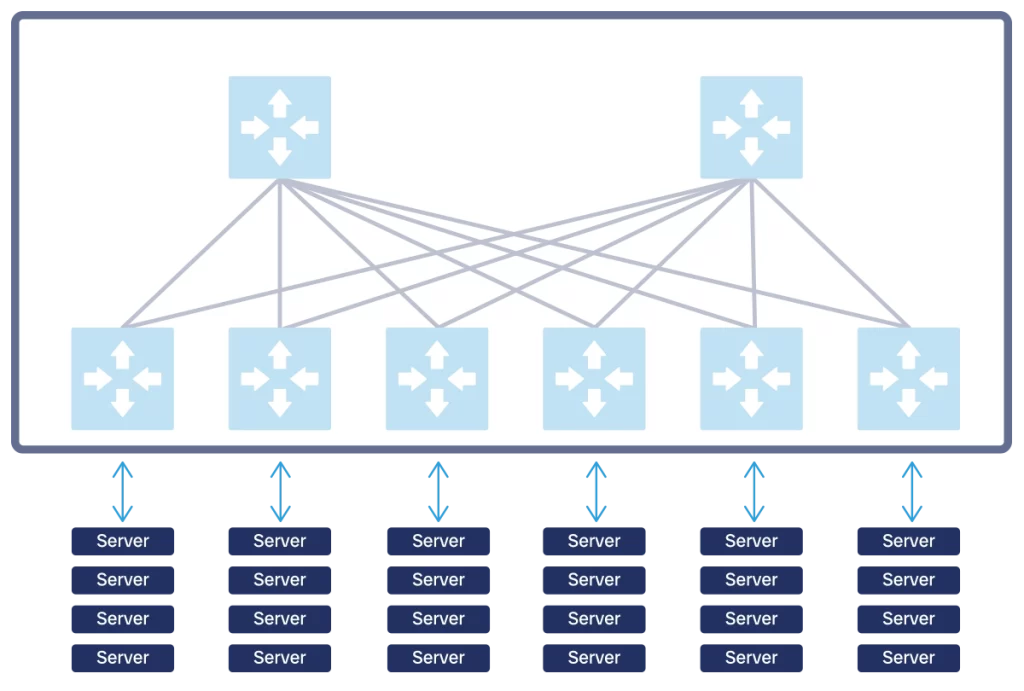
The implication of this view is simple: for our customers, the network is “one thing”, it is the fabric itself. For us, who need to design it, we need to care about how we thread its pieces together. Our customers will always see our network as a single “huge device” where they can plug in their servers. If it is one huge device, or thousands of devices cabled together wisely, our customers won’t really care.
This “fabric view” of the network highly influences the way we design it. Customers will connect their devices to the network in some specific points, which we call interfaces. We need to work to define clear and consistent interfaces, as they is the boundary of responsibility between us (the network) and our customers.
To do that, we need to introduce the concept of “layer”. A network layer is a set of devices that have the same purpose, and that can scale horizontally if you require more capacity. For example, a network layer can be “TOR”, our top-of-rack switches. If we have more compute racks we just need to add more TORs. The new TORs won’t have a different role than the previous one, they are added alongside the first group, and this is why we say we scale “horizontally”.
Typically, we define only one network layer to be the interface with your customers. Most of the time, that’s the TOR layer. We also have other network layers “deeper inside” the network, that manage connectivity between TORs. We’ll see more about those in future lessons.
Data Plane
L3 Traffic Only
In a network, the data plane is the logical component that takes traffic from device A and brings it safely to device B. The data plane is effectively what the network is meant to do. Here we find connections between devices, IP addresses, and routing tables (but not routing protocols, which are in a different plane).
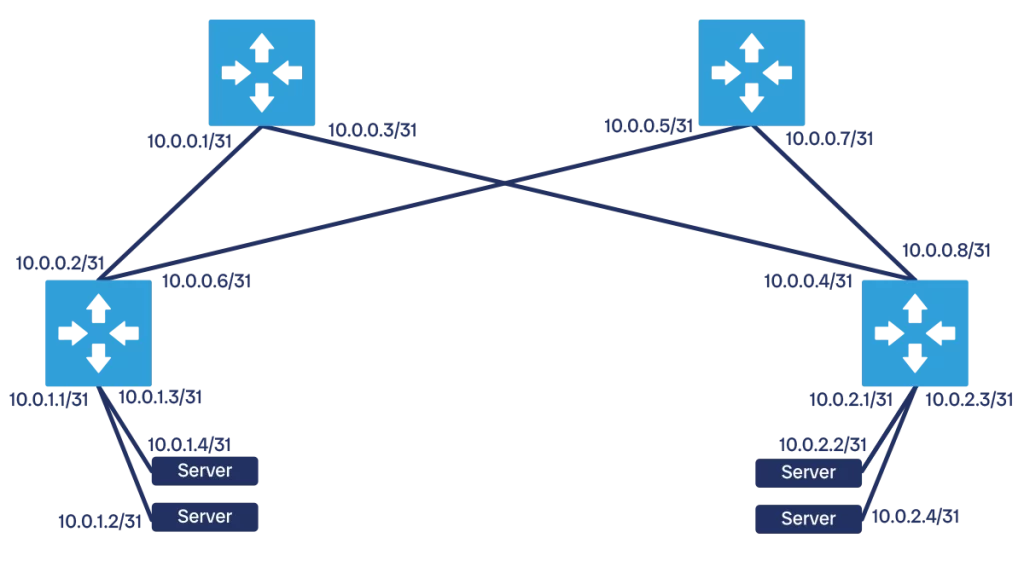
In a modern datacenter, all communication happens at L3. This means each physical port on each physical device is assigned an IP address. A pair of devices is connected on the same network segment or subnet, which is typically a /31 as it only needs two IP addresses (one for each device). This applies to switch-to-switch communication, but also switch-to-server communication. In fact, servers virtualize multiple machines and need to run multiple network segments.
To say it in another way, we have no L2 in the modern datacenter. That is the kind of communication that relies on MAC addresses and broadcast messages to figure out where a device is in the network. This comes with multiple disadvantages: it is slow to converge (find out where a device is), and it is extremely prone to loops. With a loop, traffic being is all over the place without reaching its destination, eventually bogging down the network to entire halt.
The only advantage of L2 communication is that it “sort of just works” even when plugging devices in a random or non-deterministic topology. But that is not something we needed for a datacenter: we want to spend time designing the best topology we can have. Plus, we want high performance and reliability, and an L2 communication cannot provide that. It even poses limits on bandwidth, as Spanning Tree (STP), a popular L2 protocol, will prevent loops by simply shutting down some links, thus removing capacity from the network.
One big vendor of network equipment advertises a “three-tiered architecture” as an option to design datacenters. In this architecture, you have L2 and STP running between servers and TORs, which they call “access switches”, and between access and their upstream network layer, which they call distribution. Some newer versions see L2 terminate on the access, and not on the distribution layer. Both are not good designs, and they bring no benefit to the table compared to the issues they introduce with L2 communication. A modern datacenter has no valid reason to go with this design at all.
Instead, let’s focus on L3 communication. All devices have IP addresses, and traffic is directed with routing tables starting from the server and going through all the network layers. In this way, you do not need Spanning Tree or complex ARP discovery processes, you do not risk network loops and maximize bandwidth. This also means we will need to rely on some routing protocols, but we will take care of that when we design the control plane.
Focus on the underlay
We want to manage the addressing space for our network fabric, deciding which IP goes where, as this will help us optimize performance. Our customers, who run the servers, also want complete autonomy on how they use IP addresses for their virtual machines, so that they can create their applications in the way they want. This can be a source of conflict.
To overcome this conflict, we create two abstraction levels in the datacenter: the underlay, and the overlay.
The underlay represents the physical or “real” network, and it is the network that provides connectivity to physical servers. Our entire network fabric belongs in the underlay, and in most cases it will not have any context about the overlay, it may not even know it exists.
Above the underlay we find the overlay, which is a logical network that runs “on top” of the physical network. This network is controlled by your customers, the owners of servers and compute capacity. Each server will run some virtual machines, and each machine will have its IP address. That IP address is managed by the server owners, and not the network owners in general.
Server owners will want to allocate any IP address they own to whatever virtual machine they choose, regardless of which server is hosting that VM. This means two VMs with IP addresses of the same subnet may reside on different servers, potentially far apart from each other in the physical network. This naturally poses a problem, as they will not get their broadcast and multicast traffic properly, and even sending unicast traffic to the subnet will be challenging.
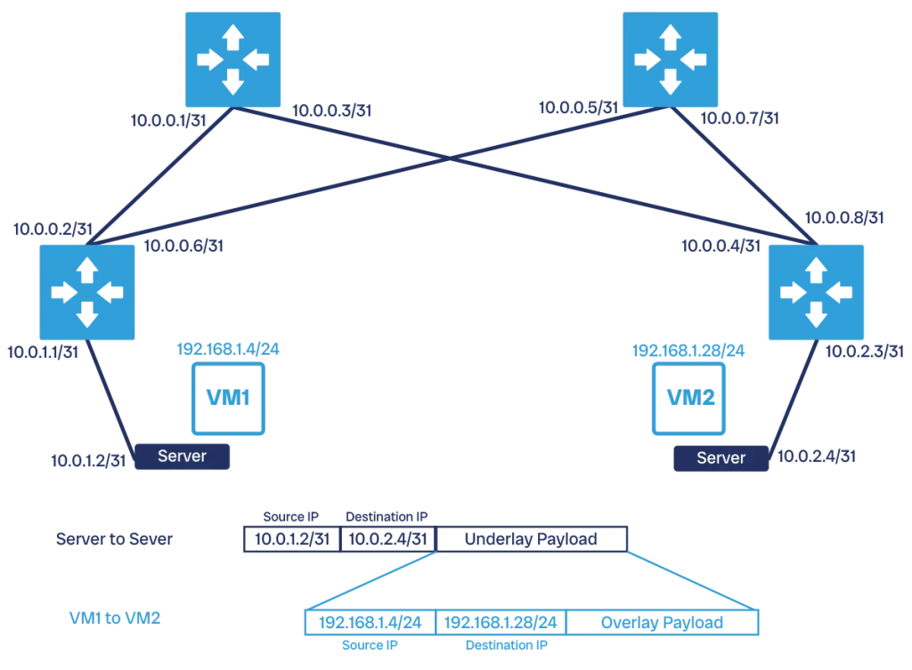
So, we need additional technology to support an overlay in our network. Specifically, we need an encapsulation protocol. With this protocol, the VM starts to send out IP packets with its own IP address. The kernel of the server, however, realizes this machine is on a virtual network and wraps the outgoing packet with a packet that has the physical address of the server.
To do this, the server needs to know which other server hosts the destination VM, and there are abstraction components to provide this information. Then, the packet goes on normally in the physical network and reaches the target server. This server will open the packet, find the inner packet destined to one of its VM, and route it to it properly. The industry-standard protocol for this encapsulation is VXLAN.
Our datacenter will need an overlay, without it we can’t have even basic features of datacenters, not to mention the limited flexibility. However, configuring the underlay so that it can support the overlay is relatively simple. Your focus needs to be the underlay, the server-to-server communication. Your colleagues working on the servers will take care of the overlay.
Core-Distribution-Access
A widely publicized design for datacenters is the Core-Distribution-Access topology, or three-tiered architecture. This became popular after it was declared best-practice by one of the top networking vendors and added to its certification programs.
However, this topology is poor network design. Yet, since many professionals are already familiar with it, or even believe it can work in the datacenter, I added this section to explain why this is really a bad idea. It might have worked in the 2000s, but that era is gone.
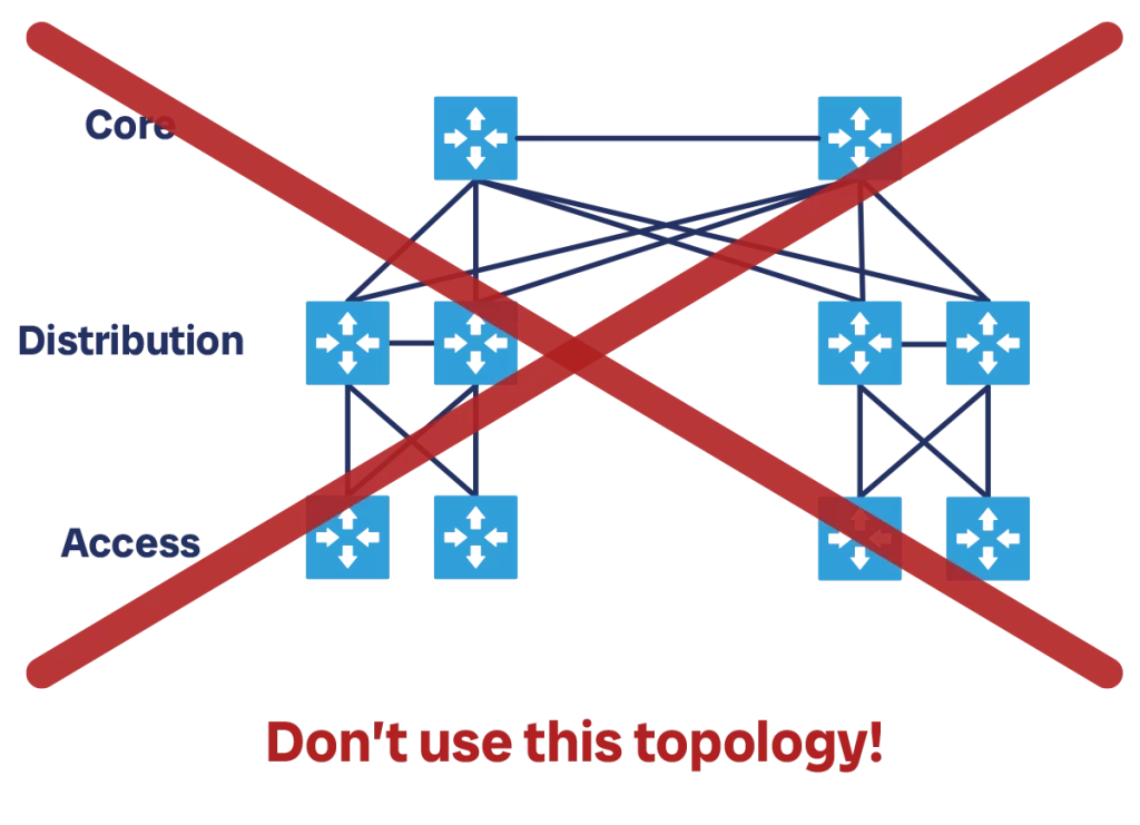
This topology uses three network layers: access, distribution, and core. The access layer is the one where you connect your servers. Access switches then connect upstream to distribution switches, which manage an “area” of the network. Finally, distribution switches connect to core switches, which handle inter-area communications. In smaller networks, distribution and core may be collapsed into a single layer, the “collapsed core”.
In this design, the recommendation is to have a pair of modular switches at the core, and possibly at the distribution layer. Those are huge switches that support the addition of multiple line card and have a proprietary protocol to failover at high speed in case one of the two was to have problems.
Each area, defined as a distribution switch and all its downstream access switches, is a single STP domain. Each access switch has a connection to each of its two distribution switches, which are also connected to one another. Each area also carries the same set of VLANs and subnets. Core-to-distribution communication is at L3, and runs some routing protocol, typically OSPF. In some recent versions of this design, STP runs only between access and servers, and access-distribution-core communication is all at L3 using OSPF.
Why is this design so bad? Multiple reasons. First, it assumes that communication is mostly local and stays within a distribution area, as distribution-core bandwidth is limited. Modern patterns in software design like micro-services made communication expand horizontally significantly, spanning outside of a typical area. Second, it cannot scale. If you want to provide more bandwidth to your access switches, you do not have an easy way.
Adding another distribution switch will require re-cabling it also toward the core. At that point, you will have one area that has more capacity, and that may strain the core. You may need to resort to add a separate distribution area and be forced to segment your network even if you did not want to.
Even with the points above, we can see this design is flawed as it simply cannot meet modern requirements. However, that is not the only issue. This design comes with significant practical concerns in terms of speed and reliability.
First, it uses Spanning Tree (STP), a protocol which relies on timers and removing links from services to prevent loops. This protocol takes time to converge, and while it does, it can leave portions of the network offline for seconds. What is worse, it may not work at all if the network becomes too big, leaving room for loops. When a loop happens, the same packet continues to cycle the network without reaching its destination, the network gets saturated and eventually crashes. This is a big concern as the impact is your entire applications, and not just a bunch of users.
For the above reasons, it is not worth pursuing this design for a modern datacenter, no matter how small or how simple you want it to be.
Subscription rate
The first design choice we must make is the subscription rate we want to apply. This decision influences how we structure our network layers and the connectivity between them.
The subscription rate defines how much downstream bandwidth we are allocating downstream, compared to how much bandwidth we are allocating upstream. Imagine we have a TOR switch that connects to servers, and it has 48x 10G ports. We can allocate 40 ports to connect downstream to the servers (40 x 10G = 400G), and the remaining 8 ports to connect to our backbone network (8 x 10G = 80G).

We express the subscription rate as a proportion, in the previous example it would be 40:8 which we can simplify as 5:1 (40 / 8 = 5, 8 / 8 = 1). Normally, this proportion is always expressed as “some number” over 1. The first number indicates the bandwidth we allocate downstream, and the second number the bandwidth we allocate upstream.
The subscription rate is a concept that applies to all network layers, not only TORs. Each layer will have both upstream and downstream connectivity, and for each layer we need to define what subscription rate we want. Of course, each layer will have its own subscription rate, we do not need to apply the same rate across all layers in our datacenter.
Whenever we have more bandwidth downstream than upstream, as it is common, we say that we are oversubscribing. On the other hand, whenever we allocate less downstream bandwidth than upstream, we say we are undersubscribing.
So, what is the best subscription rate? There is no definitive answer to this question. To choose a subscription rate, we really need to know the traffic patterns of our applications. If our servers talk a lot locally, but rarely exit beyond the TOR, then we may have a high oversubscription rate (use a lot of bandwidth downstream, and not much upstream). Instead, if we know our traffic will go more toward the rest of the network, or that we start with fewer servers and we will add more in the future, you we want to prepare an undersubscribed setup.
Again, the same applies to other network layers within the datacenter network. If their clients mostly talk with each other, oversubscribing is fine. Instead, if they want to send a lot of upstream traffic, undersubscribing may be a better option.
Remember that there will be two things stress-testing your subscription rate. On one end, we have the traffic for each of our clients and upstream destination generate. On the other hand, we need to consider how many clients and upstream destinations we have. If we plan to add more clients in the future, or more upstream destinations, we need to ensure that we have available ports and consider how this will affect our subscription rate.
Generally, a common subscription rate in datacenters is 4:1 (1 unit of upstream bandwidth each for units of downstream bandwidth).
Equal Cost Multipath (ECMP)
The next design pattern we need to consider for our datacenter network is Equal Cost Multipath, or ECMP. This is a simple concept: taking two devices in the network, we want to have multiple paths for them to communicate, each of which is equally valid.
Let’s unpack this definition. We generally apply ECMP to server, or other “edge” devices that connect to your fabric. Our fabric provides a way for, say, server A to reach server B. As the owner of the servers, we don’t care, and we just know the fabric will guarantee this connectivity. Instead, as a fabric owners, we need to consider how to make it happen.
In the simplest scenario, we have one network device connecting to both server A and server B. For A to reach B, it needs to send traffic through the network device (let’s call it N1). This is simple and works well, however it has a limitation: we have just one path, composed of two cables and one network device. If either cable is broken or if N fails, your communication stops.
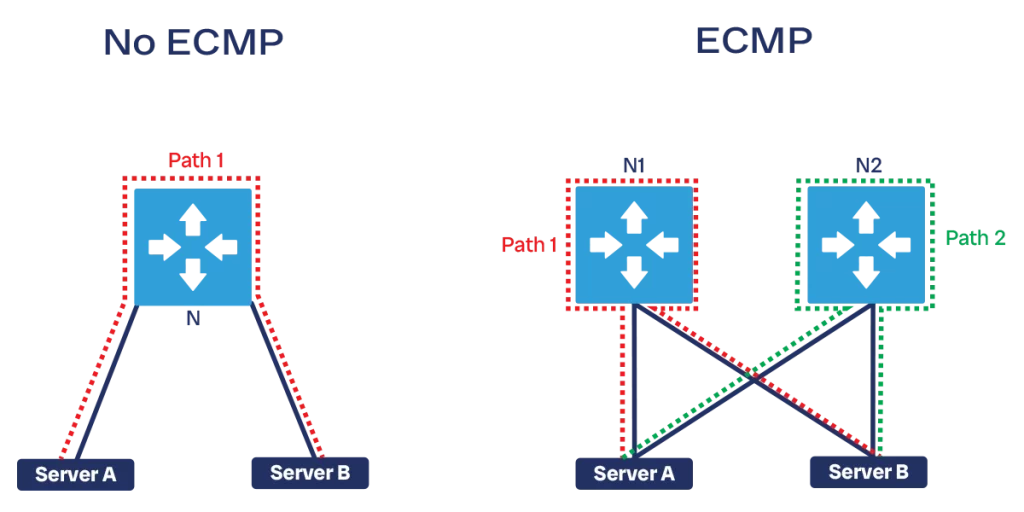
The next immediate step is to add one more network device, say N2, and have two cables toward each server, A and B. At this point, we have two paths between A and B: if one path fails, we still have the other, and there is no Single Point of Failure (SPoF) in the network.
However, we do not want our new path (the one through N2) to be sitting idle and waiting for N1 to fail. In fact, if we are using the same type of cables and network devices, it means the N2 path can provide the same bandwidth as the N1 path. In other words, 50% of the bandwidth our network can provide goes through N2. We don’t want to leave this bandwidth wasted.
So, we configure our network to use all paths available. This is easy if all paths have equal costs: each path can provide the same bandwidth. It is easy because it means all paths are equivalent, so picking one over another doesn’t make a difference. Thus, you can easily send some traffic over a path and some other traffic over another path, without too much “traffic engineering” (that is, thinking what kind of traffic needs to go where).
We have seen an example with two network paths, N1 and N2, but this can grow. The more paths we have, the more bandwidth is available, since we can use all the paths at the same time. Furthermore, the more paths we have, the less impactful the failure of a single path becomes. For example, if we have 2 equal paths a failure results in a 50% drop in bandwidth. If we have 10 paths, a failure is a 50% drop in bandwidth (5 times lower).
This approach has two design implications. First, we need to ensure we give multiple paths between the endpoints at the end of our fabric. Second, these paths must be equal cost. In other words, we need to use a consistent type of cables and network devices across the devices in each of our network layers, so that they all provide the same bandwidth. Different layers may use different devices, but within the same layer you want to have total uniformity.
Spine-and-leaf in principle
Spine-and-leaf is a network architecture based on ECMP that specifically addresses datacenter network design.
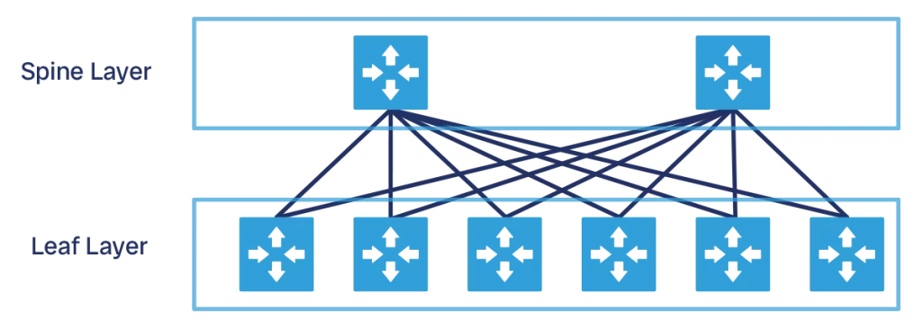
This architecture has two network layers: leaf, and spine. The leaf is typically a TOR switch, and it connects directly to your endpoints, like servers. The spine has only one function: connect leaves with each other and provide good bandwidth to them.
Each leaf connects to all spines, so that each spine connects to all leaves as well. As a result, if you have 4 spines, you have 4 equal cost paths between any two leaves (through spine 1, 2, 3, and 4). You add leaves to increase capacity (support more servers), and you add spines to increase bandwidth (support more traffic). This design can easily scale horizontally, because you can add one spine or one leaf at a time. Furthermore, the scaling of leaves is independent of the scaling of spines, they can grow at different rates.
One important point to remember is that the spine only connects leaves. So, if we have a datacenter with many servers and then a provider connection to reach the Internet, the provider connection will not be attached in the spine, but in a leaf instead. We use this approach so that the spine can have a simple configuration and focus on its important task: providing high bandwidth. Typically, we call the leaf where we have Internet providers and other external connections as the exit leaf.
All our spine-and-leaf topology is L3 only, and it runs an Interior Gateway Protocol (IGP), either OSPF or IS-IS (as link-state protocols are more reliable than distance-vector). We also do not want to run BGP within the network because it is slower to converge than any IGP, but we will use that to interact with servers and external connections.
Spine-and-leaf connections
We need to be mindful about how we use connections within our spine-and-leaf network: which devices connect to which others, and why.
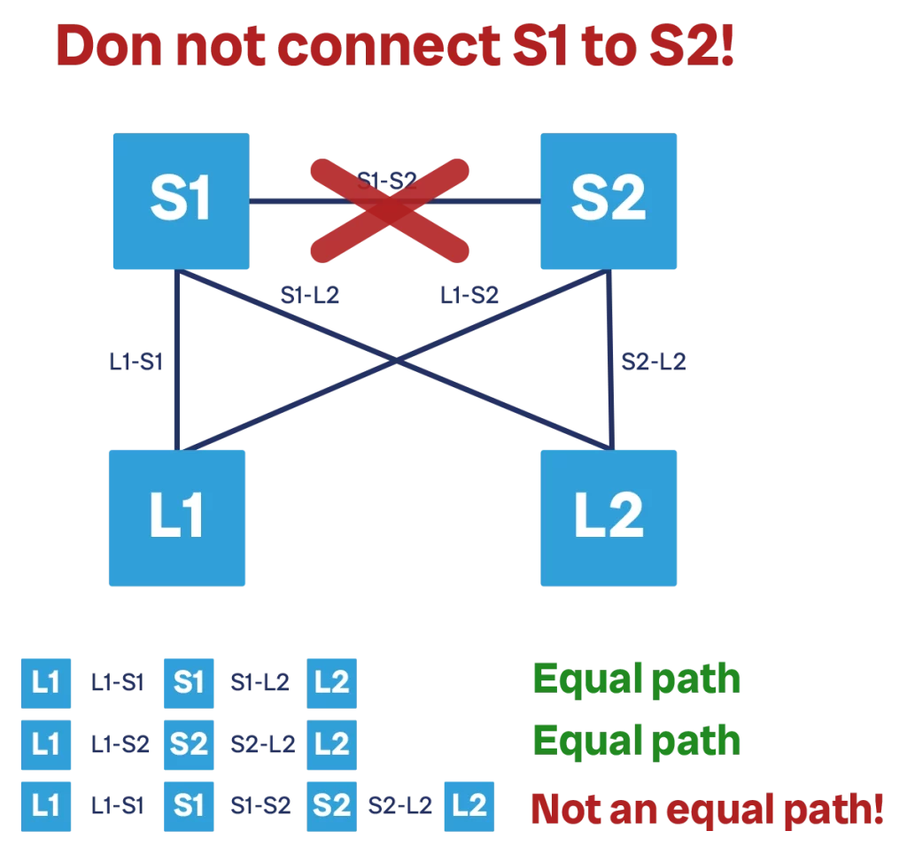
The first point to highlight is that spines are not connected with each other. Some people wonder why, figuring out that “one more link can help, or at least do no harm”. But this is not really the case for a spine-and-leaf topology. Instead, it introduces a problem by creating a non-equal cost path between devices. In a correct setup where we have two spines, S1 and S2, the path between two given leaves, say L1 and L2, can either be L1-S1-L2, or L1-S2-L2. Both paths have the same bandwidth and latency, and thus cost.
If we introduce a S1-S2 link, we create one more available path: L1-S1-S2-L2. This adds no additional redundancy, because all the failure scenarios are already covered by the “normal” spine (if either S1 or S2 fails, we already had an alternate path without the S1-S2 link). This path introduces complexity, because it still leverages the same L1-S1 and S2-L2 links, so when choosing this path, we consume bandwidth used by other paths as well. And, of course, this path adds more latency, as it adds one more hop, so we would never chose it anyway.
Additionally, we are using at least two physical ports to create this path: one on S1, and one on S2. These ports could have been used to connect more leaves, so we are “robbing” network capacity.
The second point is the connection between TORs/leaves and servers. We typically want to have two TORs, or leaf switches, and have all the server in a rack connect to both TORs. This depends on our SLA requirements, in some cases using a single TOR will be just fine. Working with a single TOR is easy, however working with two TORs is somewhat more challenging as we have two devices that need to behave as a single leaf.
To make dual-TOR scenario work, our servers must have routing capabilities. Both TORs will connect to the server and will both advertise a default route over L3 connections. Then, the server can decide how to distribute traffic to them. Typically, we want a dynamic routing protocol adjacency between servers and TORs. In most designs, this is BGP as it is reliable, and you don’t need fast convergence (because the TOR-to-server topology is small).
If we have dual-TORs, then the two TORs should connect to each other so that they can act as a single unit. If we lose a TOR-to-spine connection, we want all your server bandwidth (thus, all your TOR-to-server ports) to be able to send traffic over the remaining spine link, managed on the other TOR. This is why in this case you want to connect TORs together. However, in general leaf-to-leaf connections are also not recommended. For example, we would never connect TORs that are in different racks.
Scaling spine-and-leaf
The spine-and-leaf topology can scale horizontally by adding more spines or leaves. However, at some point we will hit a limit: a switch has just so many ports.
Let’s go through an example to make this clear. We are working with 48p switches with a 4:1 subscription rate at the TOR, meaning that we need 1 spine-to-TOR connection for every 4 TOR-to-server connections. If we operate at full capacity, each of our TORs will have 32 downstream links toward servers, 8 upstream links toward the spine layer (32:8 = 4:1), and 8 TOR-to-TOR links.
If we start with 4 spines, each TOR-to-spine connection will be a bundle of two links. This means each new spine we add needs 2 ports for each leaf, and each leaf we add will connect with two ports of each of the four spine devices. If we need more bandwidth we cannot scale, because we do not have more ports on the TORs.
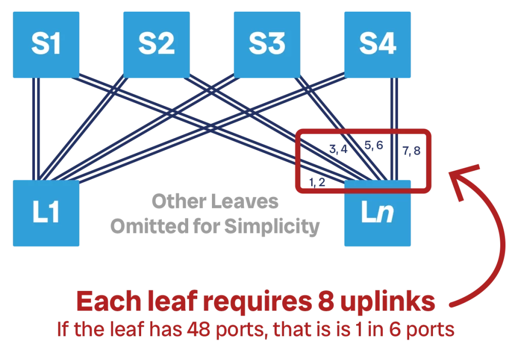
However, we typically do not start at full capacity. We may not have all the servers in place, so that we have only have 16 active downstream ports for now, and thus we need to provision only 4 uplinks, with 4 ports empty for later use. We can now connect one single link to each spine. If we run out of bandwidth, we can add more spines, say 4 more spines, and use the 4 empty ports to connect to the 4 new spines. At this point, each leaf is connected to 8 spines. And, of course, we can add the new spines one at a time as our need grows, we do not need to immediately add four.
This second scenario where we have a single TOR-spine link is preferrable because it consumes fewer ports on each individual spine device, thus it allows us to scale bandwidth with flexibility.
Even in this scenario, our spine switches have 48 ports only. This means that we can only have up to 48 leaves or TORs, each connected with one cable to each of the 8 spines. At this point, we run out of capacity in our spine and we simply cannot scale. If we add one more spine, our TORs won’t have a 9th port to connect to it. If we add one more TOR, our spine won’t have a 49th port to accommodate it.
An intermediate solution to this is to split the spine. If we have dual-TOR, we can connect all the TOR-1 devices to the first half of the spine (say, spine 1 through 4) and all the TOR-2 devices to the second half (spine 4 through 8). This effectively creates two parallel spines with four devices instead of a bigger one with 8. This saves 50% of ports on our spine, a big saving! This means now we can add up to 96 racks in our topology with 8 spine devices.
For simplicity, we show a similar example with four spines instead of 8. In this example, the TOR-1 connect to spine 1-2 (the first half), and TOR-2 connect to spine 3-4 (second half).
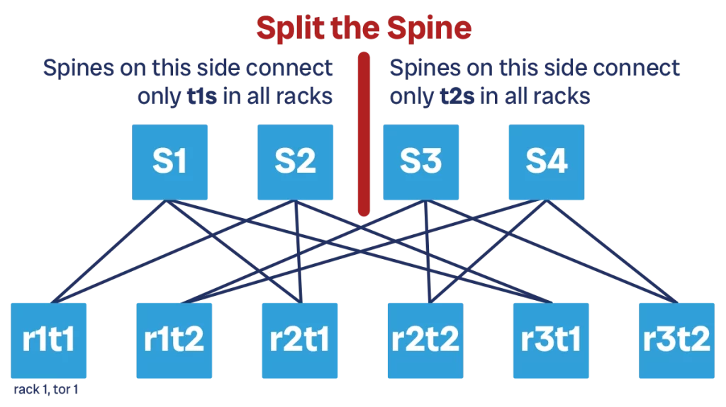
Yet, at 96 we will still hit a limit that we cannot overcome. Furthermore, scaling bandwidth is still a problem, because we need to add new spine devices to both the first and the second portion of the spine. We also do not have the possibility to further split the spine into four, as we have only two TORs per rack, and not four.
We need a different approach if we want to scale to thousands of compute racks.
3-Stage Clos Topology
The evolution of spine-and-leaf architecture is the Clos topology. In fact, spine-and-leaf is just one type of Clos topology, the smallest one. Clos is what we use in a modern datacenter and will be the focus of the next few sections.
Before we start, it is worth noting that “Clos” is not an acronym, it is the last name of the person who formalized the math behind this topology in 1952: Charles Clos.
This topology was originally designed for analog phone networks, which are circuit-switched and not packet-switched like modern networks. In a circuit-switched network, before two devices A and B can communicate, a communication path must be established. In the old days, you will have a person connecting cables on a phone switchboard to create a physical path between “phone A” and “phone B”. Once this circuit is established, all communication goes through it, and always through it. You define a path in advance, and then you use it.
Packet-switched networks are more flexible, because they do not require a dedicated circuit between two devices. Instead, communication is fragmented into packets, each containing a small piece of data, and then each packet is sent on the network. Each packet can potentially take a different path, and the path does not need to be established in advance.
Still, the logic we apply to design circuit-switched networks is useful for packet-switched networks as well. In particular, we can use the math behind it to design a network with enough equal-cost multipaths, and know in advance how many potential paths we will have between two given devices.
To start doing this, we need to revise our spine-and-leaf topology. In traditional spine-and-leaf, we have the spine at the top and all the leaves below. For Clos, we have to move some of the leaves at the top. We end up with some leaf devices, a spine at the center, and so other leaves at the top. Physically, the topology is still the same, and all devices are cabled in the same way. However, logically the change is important. In fact, we now have three network layers.
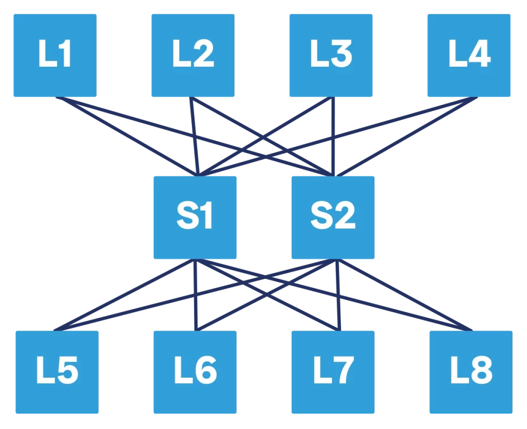
The idea is that we have network devices at the bottom of the topology that want to use the Clos network to communicate with each other, or to communicate with other devices at the top. For our purposes, being at the top or at the bottom does not really matter, it is still a spine-and-leaf after all.
As we will see later, a Clos topology can have many layers to support more capacity and bandwidth. Since the number of layers may vary, calling them spine/leaf becomes impractical. Instead, we simply start to call them “Tier N” where, the N is replaced by a number, for example T1, T2, T3 and so on. T1 is the “spine” layer closer to the TORs, T2 is “spine” above that, and so on.
Parameters for a Clos topology
Conceptually, a Clos topology is a spine-and-leaf topology where we have some leaves on one side and some other leaves on the other side. However, we have a much more elegant way to describe our network.
We can describe any Clos topology with three integer numbers, which we call n, m, and r. Let’s visualize our Clos network horizontally. We have both ingress and egress switches (at the left and right respectively): those switches are in equal number, and that number is “r”.
Each of those switches in turn will have several ports connecting to ingress or egress devices, typically servers. The number of these server-facing ports on each ingress/egress switch is “n”. Note that we are referring to the number of ports on a single switch, not the total.
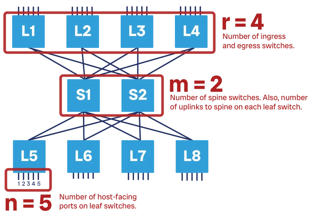
Finally, “m” is the number of switches in the spine layer. This also corresponds to the number of spine-facing ports on both ingress and egress layers. This is because each leaf must be connected to all the spines, so it must have a port for each of the spines.
In the example above, n is 5 because we have four downstream ports per switch, r is 4 because we have 4 ingress switches and 4 egress switches, and m is 2 because we have two spine switches. Furthermore, each ingress switch also has 2 ports going to the spine. The same applies to egress switches as well.
By tweaking n, m, and r we can design different types of Clos networks. The relationship between these numbers will influence the bandwidth and resiliency that we can provide.
There is one caveat here you need to consider. Using these numbers in this way works as long as all ports provide equal bandwidth. If we have one port that provides 10G, and other ports that provide 40G, then the math won’t work because a single 40G port would count as 4x 10G ports. In general, is preferrable to have same-bandwidth ports.
Designing a Clos network
Like any part of the data center network, we design the Clos topology by keeping in mind our requirements. Designing this network is simple, because Clos is a well-defined pattern with specific rules. What we need to define is the number of downstream ports, the number of leaf switches, and the number of spine switches. That is, we need to define n, r, and m.
This is not trivial. For example, is it better to have 10 switches with 20 downstream ports each, or 20 switches with 10 downstream ports each? Of course, there is no absolute right or wrong answer, it depends on case by case. But there are rules to find the best solution in any given case.
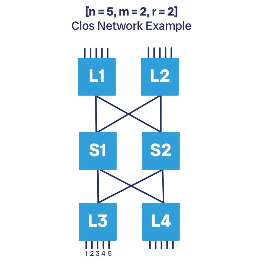
The more ports per switch we use, the denser our Clos network will be. That is, we will leverage it more, fully benefitting from the bandwidth our hardware is providing. However, we won’t be able to scale much within the same Clos without adding leaves, spines, or even a parallel Clos network in extreme cases.
As a rule of thumb, if we start with half-empty racks and server folks will come in to add more servers at some point in the future, then we should have more switches with some ports left for future growth. However, if racks a standard-designed and no new server is added to a rack, but instead the datacenter scales by adding new racks, then going for a denser network is preferrable.
Let’s consider a 32x100G ports leaf switch that uses optical modules. Each port can be split to provide 4x25G interface, thus giving us 128x25G ports. Based on the traffic patterns of our applications, the standard subscription rate of 4:1 will work fine.
The most efficient combination would be to have 100x25G downstream ports and 25x25G upstream ports. However, going upstream, it makes more sense to go in multiples of 4. This is for simplicity of the configuration. If we use 4 logical ports out of the same physical optical slot, we could simply use the entire optical slot as a single 100G port. So, it makes more sense to use the entire slot in the leaf-to-spine connection.
Thus, the most efficient real combination would be to have 96x25G downstream ports and 24x25G upstream ports, which translates to 6x100G upstream ports. Thus, we also found the number of spine switches that we need: 6.
How many ingress/egress switches can we have? Each leaf switch consumes exactly 1x100G ports on the spine, and the spine is still a 32x100G switch. So, we can have a total of 32 leaves, or 16 ingress and 16 egress switches.
To summarize, we end up with n=96x25G, r=16, m=6. However, let’s express it in integers by rationalizing the bandwidth to 100G (thus, we need to divide n by 4 as 25Gx4 = 100G). n=24, r=16, m=6. Then, we can use these numbers to evaluate special properties of our Clos.
When m >= 2n -1 we have a “strict-sense non-blocking network”. That is, each ingress server can create a unique path or circuit with any egress server, without interfering with others. In other words, taking server A and server B, they can communicate through a series of ingress and egress switches as well as spine switches and cables. If another pair of servers comes in, they can establish communication without using the path already in use by A and B. This can be repeated until all servers have established connections.
This pattern was important for circuit-switched network, where a single device was unable to handle multiple communications at once. However, it is no longer a requirement for packet-switched networks.
If m >= n, then the network is “rearrangeably non-blocking network”. That is, any two pairs of servers can always establish a dedicated path, but this may require rearranging how existing servers are connected. This is also no longer a requirement for packet-switched network.
In all other cases, the network is blocking, but since we use packets and the upstream bandwidth need is typically lower than the downstream bandwidth need, it is not a problem. However, if we have a blocking network (m < n) it means that that network can potentially have congestion. Most modern datacenters are designed to not be in congestion “most of the time”, but not to be 100% congestion-free, as this would mean having a lot of unused bandwidth on standby for peak traffic.
Multistage Clos network
For what we have seen so far, the Clos network is not that different from the spine and leaf in terms of scalability. Even with high-performing switches, we ended up serving only 32 dense racks. What if we want a data center with 100, 1000, or even 10k racks?
The Clos network is still the solution here. However, we need to go beyond the 3-stages we have seen. In the previous examples, our network was structured in 3-stages: ingress, spine, and egress. Or, to say it another way, tor, t1, and tor.
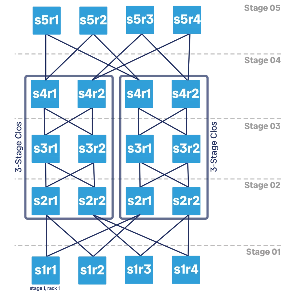
Clos networks can extend to multiple stages beyond 3, provide the number is odd. It is common to have 3, 5, 7, or 9 stages in a Clos network, depending on your scalability requirements. Beyond 9 the network starts to get too big, and there are other scalability options to consider rather than simply going to 11 stages. We will see them later. However, at least theoretically, you could have a Clos network with any odd number of stages, even thousands.
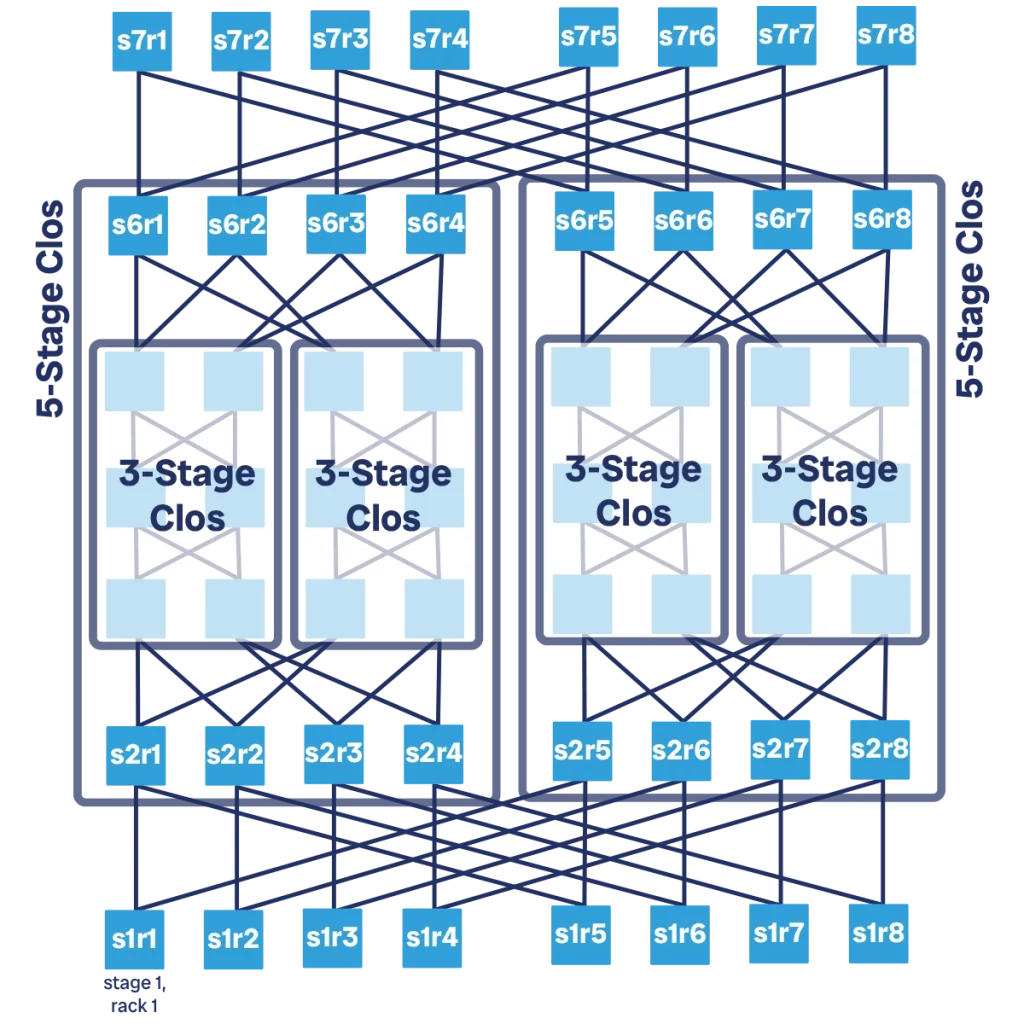
Adding more stages to your Clos network can be seen as “nesting” Clos networks one into the other. First, we start with a simple 3-stage Clos network. The entire 3-stage Clos network will become our spine. However, it does not have enough bandwidth to do it, so we create another 3-stage Clos network to put next to it. We now have the first 3-stage Clos network as our “spine 1”, and the second one as our “spine 2”. We can then add ingress and egress layers to this virtual spine.
Adding two more stages, going from 3 to 5, doubles our ingress and egress capacity. We can repeat the same process and go from 5 to 7 stages. This results in twice the capacity as a 5-stage Clos, or 4 times the capacity of a 3-stage Clos. Finally, a 9-stage Clos network has 8 times the capacity of a 3-stage Clos.
There is no logical limit to the number of stages we can have. The main limit is cost, as the more stages we add the higher the number of spine devices we need, in proportion to the number of tor devices. Thus, the cost of our overall network fabric starts to increase, and the cost per downstream port increases as well.
If we use the same 32x100G ports we used in the previous example, a 9-stage Clos can support a total of 256 racks. Going beyond that requires a different approach.
Network “bricks”
Beyond 9-stages Clos, adding ingress/egress layers starts to become an expensive way to provide bandwidth. It is also not efficient as we are not optimizing upstream bandwidth. Servers want upstream bandwidth to communicate with other servers and the Internet. The further we go up in your Clos network, the more servers we find “downward” from our position. To say it in other way, the remaining traffic that needs to go up is only the one to the Internet at some point, which is only a portion of the traffic your servers are sending.
Thus, you can consider a different subscription rate beyond a certain point, typically more oversubscribed than downstream.
To do this, we can start to consider our Clos network as a single unit. The Clos network and its compute racks can be seen as a room in our datacenter, or even as a small datacenter of its own. Instead, if we consider only the Clos network itself without the compute racks, we can call it “block”, “module”, or “brick”.
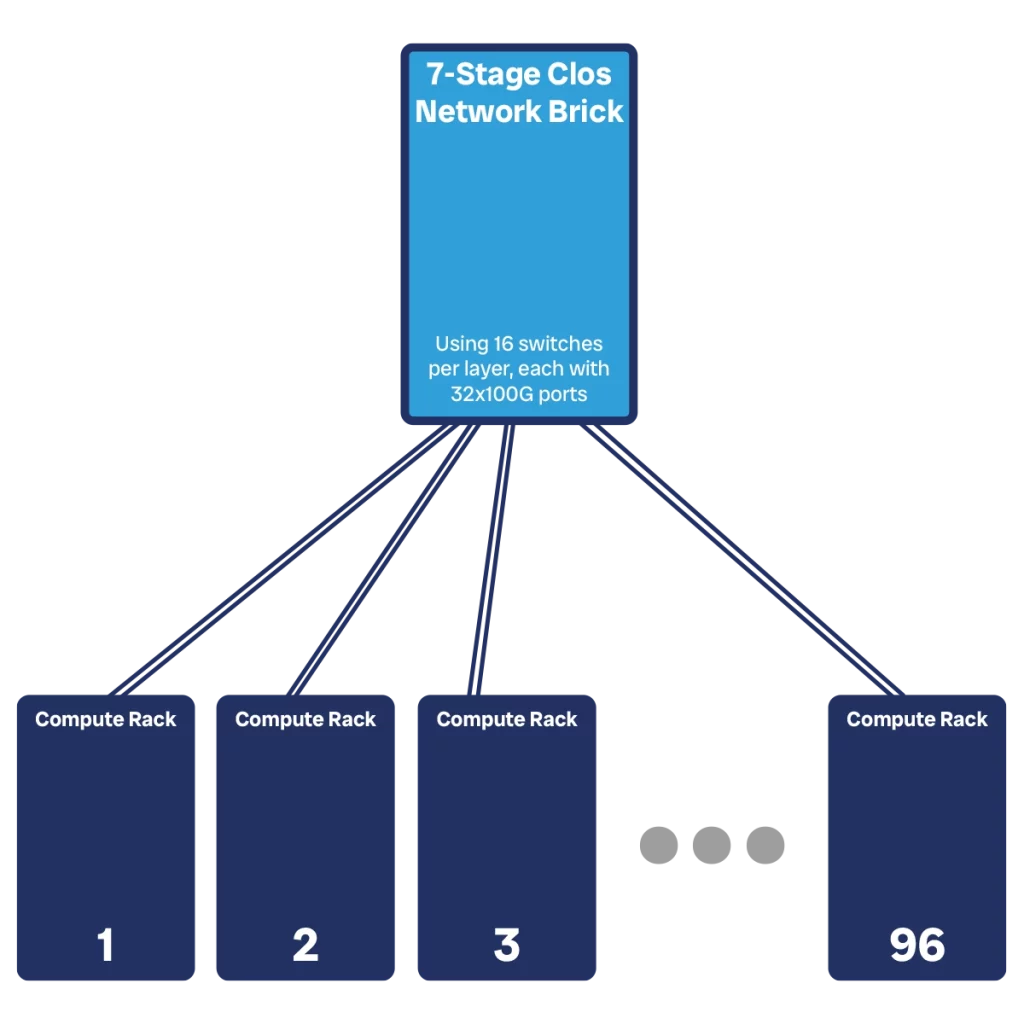
In practice, a Clos brick translates into one or more network racks in the datacenter. If a 3-stage Clos network was 6 switches, then it means we can squeeze two into a single rack, making the spine of a 5-stage network fit into a rack. To create the spine of a 7-stage network we will need two racks like that.
Instead of having servers on the egress side, which is upstream, at the top, we can now have connections toward other bricks. We would need to create a mesh of bricks, where each brick is connected to each other. We will encounter troubles if we want to scale this, as we will run out of ports quickly.
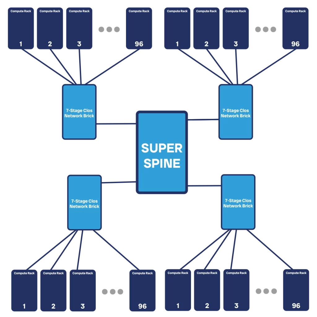
A much better way is to create a superspine. This is another Clos network, typically of the same size of any you would use to connect compute racks. However, the role of this network is just to connect other bricks. At this point, we are really starting to create another Clos topology, only that each node is no longer a switch, but an entire brick composed of multiple switches.
Tiered datacenter with bricks
With the concept of brick, we can start to see how our datacenter can scale to massive size. Beyond a certain dimension, we want to start to partition your datacenter. This is because of multiple reasons.
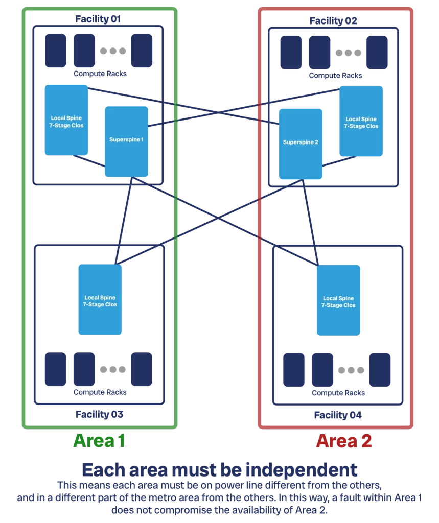
First, we do not want to have everything in the same place. If something bad happens there, like a fire or a weather event, we may risk our entire DC. Second, finding suitable lands and buildings is hard, and securing power is even harder. A data center consumes incredible amounts of energy and having that available in a single place is not obvious. A 256 racks DC with 30kVA per rack can consume almost 8MWh, and this does not include the power needed for network gear and HVAC. That is about what 10 US households consume in a month, condensed in a single hour.
So, we split our data center network across multiple facilities. In any given facility we have a brick providing bandwidth to all the compute racks. Typically, this is a 7-stage Clos which provides the best cost/bandwidth efficiency. Still assuming the same 32x100G switches, we can serve up to 64 ingress compute racks. However, we are unlikely to need 64-racks-equivalent capacity to go upstream. We can thus move some of the upstream capacity downstream. We could decide to have 96 racks at the ingress layer, and leave 32 of upstream capacity. This is a generous 3:1 subscription ratio.
Now is the time to create our superspine. Physically, this may be located in the same facility of our main (or first) datacenter, or it can be in a separate facility together. To compute the size of the superspine we use the same logic as a traditional Clos network. However, the units of bandwidth are much bigger in this case. Instead of considering the single 100G port, let’s consider using an entire egress switch to provide connectivity to the spine. Considering we have 24x100G egress ports, this means a 2.4T unit.
We have a total of 32 egress switches in each brick. We will connect each of those to one switch in the superspine. The superspine will have its internal spine as well. For simplicity, we can assume the spine will be a standard brick that must serve 32 leaves (let’s not make distinction between ingress and egress at this point). If the subscription rate is consistent at 4:1, the same we had between the local bricks and the compute servers, this means we still have 6x100G upstream ports and a total of 6x T1 devices, we can have a 3-stage Clos spine network. If bandwidth requirements increase, we can expand it to a 5-stage Clos.
Even with just a 3-stage Clos superspine, we can serve multiple datacenter locations for a total of 3072 racks, or 92MWh. If we create a superspine with a 7-stage Clos, we can serve 128 locations for a total of 12,288 racks, or 370MWh.
Finally, we could go beyond this and create an additional super-superspine. The logic is the same, we reserve some switches as egress in your superspine and use them to connect to the super-super spine. If we have 7-stage superspines and we carve out 32 out of 128 switches as egress to connect to the super-superspine we could potentially connect up to 9.4 million racks for a total of 283GWh. This is more than the total power generated by a small country like Sierra Leone (244GWh).
Theoretically, we could add as many layers of spine as you want. However, this is also impractical and goes beyond current data center needs and requirements. Furthermore, we start to hit scaling limits in terms of hop count of devices (number of devices we need to travel to go from point A to point B). Of course, the lower the better.
Fault scenarios
We conclude the data plane section of this data center network design guide by discussing potential fault scenarios. The network won’t be infallible, devices will occasionally break. In fact, the more devices we have, the more are breaking on any given day. Additionally, there are other events that can endanger your datacenters: extreme weather, power shortages, fires, and fiber cuts are the most common.
To design a sound data center network, we need to consider what are the possible fault scenarios, what is the impact on your network fabric, and whether that impact is acceptable. If it is, then good. If not, then we need to adjust our datacenter design until it is.
The first consideration is that our fabric should have no Single Point of Failure (SPoF). There should be no single device or single brick that is the only way for some other devices to communicate. Otherwise, when that device fails, communication will be interrupted.
Depending on our SLA, we may allow for some SPoFs at the edge of the network. For example, if we have a 99.9% SLA it means you allow for almost 9h of downtime per year. We could consider having a single tor device in each rack, with one ready spare tor available every “x” active TORs. When a tor fails, we need to have people quickly replace it within 9 hours.
If we assume a meantime-between-failures (MTBF) of 5 years and we have 3076 racks, and thus 3076 TORs, then we can expect about 615 to fail in a given year, or about 2 per day. It seems manageable for a person to handle. However, we need to consider that our DC will span across multiple locations, and that if we buy all TORs when we create the DC, then they will all reach their end of life around the same time.
In general, it is preferrable to have no SPoF at all, not even in TORs. If we have no SPoFs, it does not mean failure of devices has no impact. A device removed from service is a reduction in network capacity for your fabric. So, we need to consider what the bandwidth of our fabric is when we have devices out of service, and see if this is still enough to meet our needs.
Let’s consider the Clos networks we discussed in the previous sections. They all had a total of 3T bandwidth (2.4T downstream, 600G upstream). Since we always had 6 spines, losing one device means halving the downstream capacity, and reducing by 1/6 the upstream capacity.
In a 7-stage clos network with n=16 and m=6 consistent across all stages we have 280 devices, with MTBF of 5 years is 56 failures per year. Let’s assume it takes 1 week to replace a failed device, it means on any given day there is one device out of service in the network.
This means the bandwidth available is 5/6, or 500G upstream. If we are fine with 500G upstream bandwidth, even if the nominal capacity is 600G, then we are good to go. If not, we may need to consider adding more spines, being faster in replacing failed devices, or a mix of the two.
Control Plane
Natural boundaries in the network
The role of the control plane in our datacenter network is to provide devices with routing information. That is, any network device in our fabric needs to know where to send the traffic it receives. Designing the control plane means defining “how” the network devices will come to acquire this knowledge, and how they will keep it up to date.
Most of the time, this information is shared between network devices through routing protocols such as OSPF, IS-IS, and BGP. However, before we can decide which protocol to use and how to use it, we need to think about how the control plane will help us in achieving our goal. How can we have a control plane that fosters reliability and maximizes bandwidth in our network?
There are two driving principles to achieve this. First, we should share the minimum information needed. For example, your home router knows that it can access the entire Internet by sending traffic to your carrier. It does not need to know the inner bits and bolts on how the provider will send the traffic to the right destination. That information is relevant only within the carrier’s backbone. The same is true in a datacenter network: a device should not know detailed information about connections in remote parts of the datacenter.
This can be achieved with summarization, a concept we will explain later in this guide. However, as we introduce summarization we add complexity. Instead, the second principle is that our network must be simple, so that it can easily be managed and expanded.
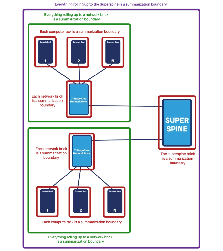
For this to happen, the “natural” boundaries of the network are an important concept that can help us design the control plane. If we see our network as a collection of devices, we can start to create sub-groups. A boundary defines where a group ends and where the next starts. Potentially, we could define any logical boundary you want. Yet, there are some that feel more “natural”, because they correspond to other existing division of responsibility.
The first boundary is the rack level. We have servers in a compute rack, and it makes sense for them to be in the same group, rather than to have servers of two racks be in the same group, and thus a group spanning multiple racks.
Then, each network brick provides another logical boundary. A network brick provides connectivity to other compute racks as a spine, and all the compute racks connected to it can be viewed together as a group (which can be further split in per-rack). Even the entire brick itself, which is just network devices, can be seen as a group of devices on-par with the rack level.
We can take this even a step further, and group together all the devices under the same super-spine brick. Or, even more, we can logically consider multiple spines or super-spines to be together, for example the ones that are physically in the same facility or datacenter campus. The important point is that these groups are not mutually exclusive, but instead nested with one another.
The boundaries we will use in the rest of the guide are rack-level/brick-level, spine level, and super-spine level.
Standardization and summarization
Once we know the natural boundaries of our data center network, we can use them to standardize and summarize. These are two important design patterns that help our network scale seamlessly.
Standardization is the concept of designing the network as a set of modular components. Each component of the same type follows the same template, which means you can create many of them easily. It is like setting up an assembly line and then producing all these components in series.
In a data center network, you have two modules: the compute rack, and the Clos brick. Each module is typically contained into a single rack, although large Clos bricks can occupy up to four racks. We may also have different flavors of compute racks, each accommodating a different set of servers.
Standardization helps us when it comes to IP addresses allocation. Each device communicating over the network needs to have an IP address, including network devices. Each address belongs to a network segment, or subnet, which often corresponds to a physical link between two devices. Sometimes, however, the network is virtualized to be “within” a device, as it is mostly common for servers.
If we know how many servers we have per rack, we know how many IP addresses we need. As network designers, we do not generally care about IP addressing for virtual machines, but only for physical servers. That’s because virtual machines are on the overlay, and servers are on the underlay.
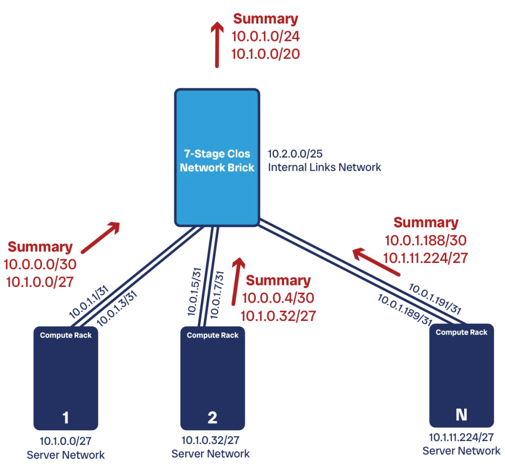
If we know how many addresses we need, we can try to create a block of contiguous IP addresses for a rack. That is the supernet for the rack, that will contain all the IP addresses for all the components within the rack. For example, if we need about 240 addresses in total in our compute rack, a /24 network (with 256 addresses) will do the job. Clos bricks may need a larger subnet, like a /23 or /22.
The advantage of standardization is that we do not need to consider within a module. If we need to scale, we add more modules, rather than expanding the network inside a module. As a consequence, we can be pretty tight with IP addresses, there is no need to over-allocate them. This is crucial when we work with IPv4, as addressing space is limited.
Once standardization is in place, it paves the way for summarization. This is a routing concept where we try to advertise, when possible, only the supernet to our neighbors. Instead of communicating information about each individual piece of the network, we bundle them together and communicate it “summarized”. For example, we do not communicate the reachability of an individual server, but of the entire rack. This is only possible when IP addresses and subnets are contiguous, and this is why standardization is important.
Our compute rack can advertise to our Clos spine only one subnet, which contains all the devices in the rack. This is much more efficient than advertising 30-50 small subnets. It also has good implications for the stability of the network, as we will see when we discuss Interior Gateway Protocol.
Routing information that matters
At some point, we all have met someone who keeps talking about things that are just not interesting to us. We don’t want to be that person, and we don’t want our network to behave like that either.
Routing protocols allow network devices to communicate with each other. They tell each other information on how to reach specific parts of the network. We don’t want a device to overload other devices with information that is not relevant. Instead, we want to share information only about destinations other devices will care to reach. And that is servers.
Imagine we have a large topology with 5 Clos spines and a super-spine connecting them. Each spine then connects 96 compute racks, each with 32 servers. Each server will care to send information to other servers, and not to the Clos network itself. The Clos network is just a means to an end, an intermediate path, and not a destination. It is the network fabric, which should be transparent to servers.
To make an analogy, imagine you are travelling from New York to Atlanta via Interstate. You can literally hop on the Interstate in NY and get out in Atlanta. You do not need to know how to reach all small towns on the way, say Gaffney SC. However, when you pass Charlotte and drive into South Carolina, you will see signs that mark the exit for Gaffney. But you do not need to know about it while you are still in New York.
Your source server is like New York, and it wants to send IP packets to your destination server, Atlanta. In New York, we only need to know we need to put the car (i.e., the IP packet) on I-81-S and off you go. The same is similar in the network. We only need to know the packet must go to the spine, but we do not care about what happens in the spine. The spine will take care of the packet once it gets it.
All this is to say that we should avoid propagating routing information of what is within a Clos brick to outside of that brick. Only propagate information about the servers you can reach downstream, and what are the destinations you have upstream.
BGP Architecture
The routing protocol of choice to propagate server information is BGP. That stands for Border Gateway Protocol, and it is designed to communicate Internet routes. It is robust and supports advanced configuration and tuning. In fact, it is pretty static in its configuration, but we will see that it is an advantage.
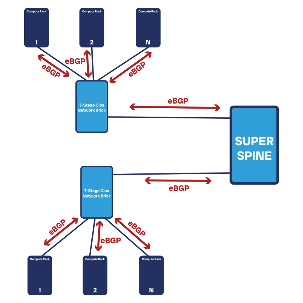
With BGP, we have to manually configure on each device who will be their peer to exchange routing information with. This may seem an inconvenience if we compare it with other protocols like OSPF that can “discover” how the network looks like on their own. However, we need to keep in mind that our network is extremely predictable. We design it to be scalable and standard, and we do not extend its functionality within a component. When we build a Clos brick, that’s done. If we need more bandwidth, we add another brick.
So, we can consider each Clos brick (whether spine or super-spine) and each compute rack as a unique component. We will see later how to work within each of those components. The big part is how those components communicate with each other, and that is where BGP comes handy.
Each component is resilient and can handle device failure (only resulting in slightly reduced bandwidth, no loss of connectivity). Thus, we find no value in sharing information about device failures (more technically “network state”) within a module to other modules. Let’s only propagate information about servers, and BGP is perfect for that.
Each edge device on each module (the TORs on the compute racks, the outermost leaves of the Clos bricks) must have 1-to-1 BGP adjacencies with their peer device from the other module (i.e. TORs peer with both servers and with the Clos fabric). Then, we need to enable redistribution so that they can carry over information from the other layers (i.e. the Clos brick will redistribute to all the compute racks the routing information it gets from a TOR. It will also send it back to the superspine).
We also need to make a choice between Internal BGP (iBGP) or External BGP (eBGP). The difference is that with iBGP all the neighborship are within the same autonomous system (AS), a “unit of ownership” of the network, represented by a number (ASN). Each module must be within the same ASN. Having different modules in different ASNs is a good practice to help your network scales, as it helps you better control the BGP peers between modules.
The final concept you need to consider is route reflectors. Route reflectors are the master brain of a BGP ASN. They collect updates from all the BGP routers within their ASN, and relay the information with each other. Without those, each BGP-running device will need to peer with every other BGP-running device. For example, in a Clos fabric each leaf would need to have a BGP peer with all the other leaves. This does not scale well.
Instead, we elect two network devices to act as route reflectors (one is primary, the other is backup) that are in charge of relaying updates. These can be any two devices, either dedicated switches or two switches part of the Clos topology. In the past, the recommendation was to put them on the leaves so as not to overload the spine. However, with increasing computational power on switches, it does not make a significant difference.
We do not need route reflectors within compute racks, as each rack has only two switches and they already peer with each other.
IGP Architecture with IS-IS
With BGP, we can make modules communicate with each other. Yet, with only BGP, each module simply won’t work. This is especially true in the Clos brick: it won’t have any idea on how to send data from any two leaves. This is what we use IGP for.
IGP stands for Interior Gateway Protocol, and it is not a protocol itself. Rather, it is a category of protocols that are designed to work within a module. We find protocols of two kinds: distance vector (DV), and link state (LS). DV protocols are legacy, each device advertises reachability information about other devices without having a full understanding of the network, but rather only incrementing counters to show that the destination is far. They are inherently prone to loops and should not be used in any modern DC. We find RIP and EIGRP in this class.
The modern class of IGPs is LS. There we have Open Short Path First (OSPF) and Intermediate System to Intermediate System (IS-IS). In both cases, each network device maintains knowledge of the entire topology: how each device is connected to which other. When something happens on the network, like a link going down, the event is propagated, and all the devices use that to update their topology. Then, they use the updated topology to decide where to send traffic.
OSPF is the most popular protocol, widely used and widely known. However, IS-IS is more scalable and has better support for virtualization. This is because OSPF uses the underlying IP network to communicate and build the network topology. It was designed for IPv4, and if it needs to run for IPv6 we need a different version of it, OSPFv3. OSPFv3 in turn can also run for IPv4, but that is not common in the industry. And we still need to decide which plane to use to propagate routing information: IPv4 can be used to carry both IPv4 and IPv6 information.
IS-IS has a different abstraction layer. The adjacencies between devices do not depend on underlying network protocol (whether IPv4, IPv6, or something else). It just build a topology of devices, which you can then use to share information about any network protocol. This makes it better at supporting both IPv4 and IPv6 scenarios, and to support virtualization of the network in general.
For example, IS-IS is used in some modern datacenter hypervisors to route information about MAC addresses, instead of relying on the L2 ARP protocol (which is slower and prone to loops as well).
So, when building a data center network, the advice is to use IS-IS as the IGP protocol within a brick. We should also use it between two TOR devices, although the main benefit is at the Clos-level. There, we can simply group the entire brick into a single topology, there is no need to overcomplicate things.
Firewalls at the edge
One more thing to mention when designing the control plane of your data center network is where to put firewalls. Or, more in general, where do you put “the edge”, where do we connect “the rest of the Internet”?
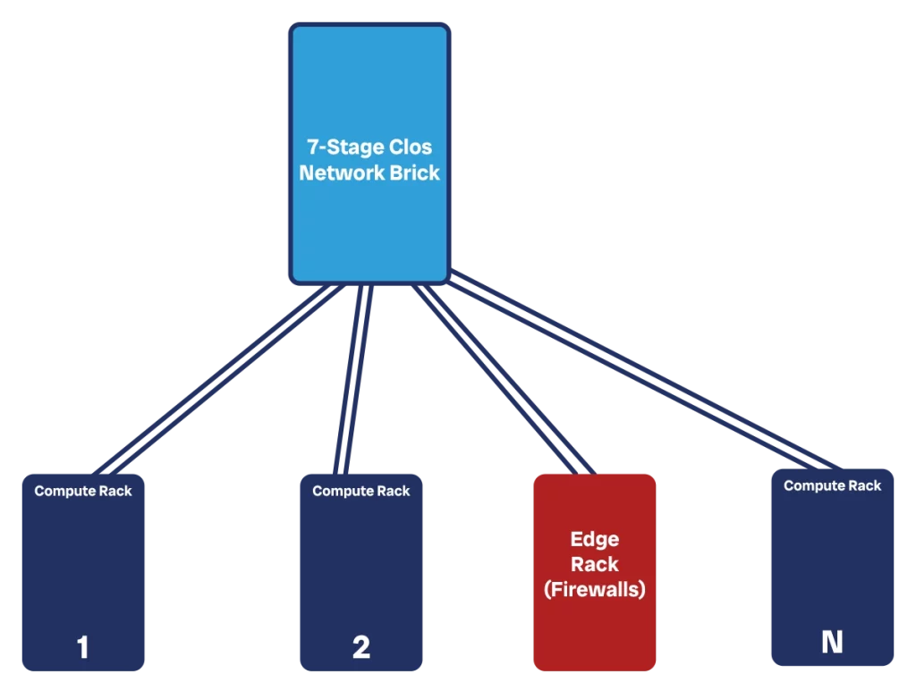
The answer, of course, is “at the edge”. We do not want firewalls or providers to connect inside the spine. Instead, we want them to be like any other client that consumes bandwidth of your fabric.
In the simplest scenario, we remove some compute racks connected to a brick and connect there your ISP. This connection happens by placing firewalls in a vertical way: we have one link going from the brick to the firewall, and then one link going from the firewall to the ISP. We do this multiple times with multiple links for redundancy, and we can aggregate links as well when needed.
This, however, may introduce some imbalances in our DC. The brick that connects the ISPs may be a popular destination and may get more easily saturated. Instead of doing that, it can be worth creating a dedicated edge brick that connects only edge devices like ISPs. This has a big benefit: we can play with a different subscription rate within this brick, based on our traffic patterns.
If we have a super-spine, we could also consider attaching your ISPs to your super-spine “as if they were a brick of their own”. However, it provides us with much better control if we have a dedicated brick to connect ISPs. This can be of particular importance if we start to have a big data center, and we want to interconnect multiple service providers.
When it comes to routing peering, just like any other module-to-module connection, we use BGP.
Management Plane
Out-of-band management
The next thing we need to look at for our datacenter network design is the management plane. This is the infrastructure we use to manage our devices. That is, what we use to see what they are doing, enable new features, and push security updates.
There are two ways to see management: in-band, and out-of-band (OOB). To manage a device, we need to communicate with it, sending packets through the network (typically SSH, HTTPS, or gRPC protocols). We can choose to send those packets across the same physical network that our servers use to communicate, so this management traffic consumes part of the bandwidth of our customers: that’s in-band.
Alternatively, we can set up a separate physical network that is dedicated exclusively to management traffic. This is OOB. As you can imagine, OOB is more expensive than in-band, but also much better.
We use the management plane to deploy changes to our devices. As part of these changes, we may instruct devices to do routing differently. If these changes go wrong, we break routing and connectivity. However, if we manage our devices through the same network we are changing, we will lose access to the device if we break it. Hence, we won’t be able to rollback, and we will have to send someone on-site to access the device with a console cable. This can get out of control quickly if we deploy to many devices at once, common if our fleet of devices is in the order of thousands.
Even if our changes are perfect, management traffic competes with customer traffic for bandwidth. If we are at saturation, something has to give. Most often, this is addressed by some class-of-service: management traffic will take precedence up to, say, 10% of the bandwidth. This means that management traffic can use less than 10% of the bandwidth, and the remaining is always available for customers. However, when management traffic wants to expand, they can grow up to 10%, limiting customer traffic to 90%. In other words, during peak times when our customers need bandwidth the most, you we reducing that for them.
If we do not implement classes of services, then anything goes. Our management traffic may get dropped during congestion, and we may still lose access to devices because there isn’t enough bandwidth.
Both situations are not ideal. Fortunately, building a management network for a datacenter is relatively inexpensive because we have a lot of device density: many devices in close quarters. This allows for some efficiency.
We can create a management rack with 2-4 switches that then connect to the console port of all switches in their near proximity. For example, we will typically arrange racks in a grid with rows and columns. We can have each management rack provide out-of-band connectivity to a given set of rows and columns. Then, these management racks act as our “compute racks” of the management network. We can build a dedicated spine for them, with a simple spine-and-leaf or Clos topology depending on the size of the network.
The management network will be much smaller than the data plane network, and will also have reduced bandwidth requirements, which means we can use cheaper hardware to run it.
At some point, our management network will need to connect to our data-plane network. That can be just a simple edge, much like we connect external providers or firewalls. In this way, computers and servers sitting in the “normal” network can reach the out-of-band network easily.
Note that OOB is not a replacement for in-band. We need to have both. In this way, we can still recover devices (even devices in the OOB network) if we were to break that with some changes.
Active and passive monitoring
In a big network, things can go wrong. We need to detect, isolate and react to problems faster. This is a key requirement for all datacenter network design, as applications that run in a datacenter are generally mission-critical for business or customers.
To detect a problem, we need to monitor the network. There are two approaches for that, and we will need both: active and passive monitoring.
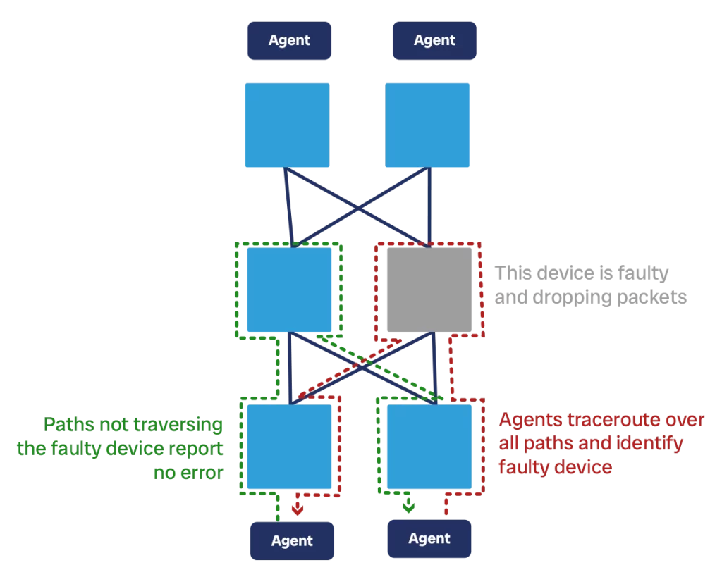
Active monitoring is the most accurate representation of customer experience. This is what we use to see if the customers of your networks are experiencing problems, such as packet loss, latency, or jitter. Active monitoring means we have something “active” to check the network status, we call this component a “canary”.
The canary is some sort of software, system, or machine that sends traffic throughout the network and sees how it performs. In the most basic version, this is an ICMP ping test. However, it can be more complex trying TCP or UDP on specific ports, HTTP, or even application-specific flows such as calling a specific REST API with some specific payload. In case of network canaries that run ICMP, UDP, or TCP, we typically have multiple canaries across the network. They send traffic to each other and expect replies. If replies don’t come, come with high latency, or come with high jitter, then we have a problem.
If we have many canaries, we can do triangulation. This means we identify the path between each pair of canaries, and then identify what is the path common to all canaries that are failing. In this way, we can isolate where the problem may be in the network.
Active monitoring in general, and triangulation in particular, requires some software development. We need to create pir own canary software to send traffic, and then some aggregator to collect information from all the canaries you have in the network.
We support active monitoring with passive monitoring. This is a simpler solution where we ask directly to network devices what is their status and if they have some problems. For example, we ask them to provide information about their CPU load, interface discards, and more. This works well to assess specific information; however, it has one major flaw. We “trust” the device we are trying to assess for health status. A common protocol here is SNMP, although it is being replaced with new API-based telemetry solutions by most vendors.
We still need passive monitoring as it provides information active monitoring cannot detect, like the CPU load of a machine. But we will need to aggregate alarm and events from both systems centrally to make sense of what happens in the network.
Shifting traffic
When designing a datacenter network, we need to design the process to shift traffic as well. Shifting traffic means removing customer traffic from a device (some people call this also “draining”).
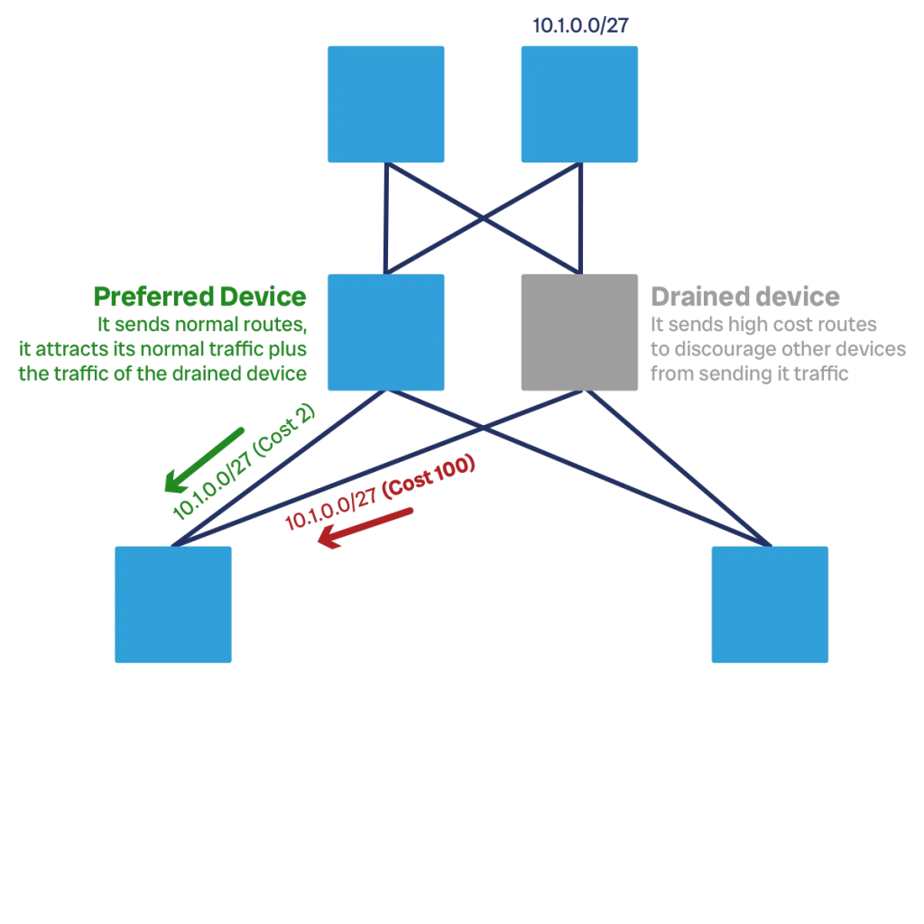
We need to shift traffic off a device to mitigate impact. If a device is behaving in unexpected ways, for example dropping some packets, we want to have a quick way to redirect all traffic out of that device and into the rest of the network until we can fix that device.
The logic to do this is simple. If we have a redundant layer, like TORs, we drain a device by shifting all the customer traffic onto the other TOR. If we have a layer with multiple components that work in parallel, such as a spine, we drain a device by distributing the load of that device to the other device in the same layer. This is sort of a generic definition: to shift traffic off a device, you need to re-distribute this traffic across the remaining in-service devices in the layer.
Even if this is conceptually simple, there are moving parts to consider. We want to assess if the remaining devices can take the additional bandwidth from this device or if they are saturated (or have other network problems), and we want to ensure we are shifting consistently. For example, we don’t want tor1 to shift traffic onto tor2 while tor2 was already shifting traffic to tor1.
We also have multiple options on how to implement the drain/undrain logic. There are two main approaches: soft, and hard.
With the soft approach, the device remains ready to carry traffic, but it is graciously asking its peers to not send it traffic anymore. This is done by increasing the costs of advertised routes, or increasing AS-Path prepend when you use BGP. The big advantage of this approach is that it won’t cause customer impact, such as unexpected packet loss during the time of shift. However, some more time to execute than the hard approach (in most of the cases, this is tolerable).
The hard approach is much more brutal. We just go there and shut interfaces or neighborship peers. This is fast, do not rely on other devices accepting routing changes, but may cause some packet drop while the network reconverges.
We may want to develop both soft and hard shift methods, and use the hard shift method only in case of an emergency. In either case, we achieve the shifting away (draining) operation and also the shifting back (undraining) operation by deploying some config changes to the device.
Another item to think about is that we can shift traffic off a device, a set of device, or even a link or span between devices. We can decide which level of granularity is needed for our use case. The more granular, the more complex to implement, but also the most efficient: shifting away means removing bandwidth from the network, we want to remove only the minimum bandwidth needed.
Deployment best practices
We need to design a datacenter network that scales. Part of this scaling also means that we can deploy new configuration and Operating Systems to our devices regularly and at scale. This requires automation, and the automation must be safe. If your automation breaks something, it breaks things at scale, something you do not really want.
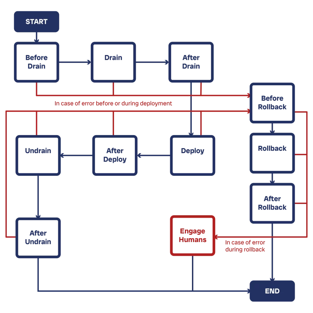
We consider a “deployment” any change that we push to a device, whether new config, new OS, or both at the same time. We can break down any deployment operations into four stages: pre-checks, actual deployment, post-checks, and rollback if needed.
Before we start to make any changes, we want to do some checks to ensure the network is in a healthy state. As part of those checks, we may also want to collect some information that we want to re-check later, for example the number of BGP peers on a device or the number of interfaces up and down. If we have everything we need, we start the deployment.
The first thing we want to do is drain the device of traffic. We do not want to perform any change, even the most trivial, while the device is life. This is a safety measure. Even if some changes may be technically safe, if we have the habit of always shifting away traffic off a device before any changes, we do not need to bother checking if the changes are impactful or not. Once the device is drained, we perform changes.
After we apply the changes, we can perform our post-checks to see the network is still healthy. If we have collected some data earlier, such as the number of BGP peers, we can check that it did not change. If everything is good, we shift back the device. Potentially, we may want to perform again the same checks after we have undrained the device, just to be sure.
If things went wrong, and our post-checks alert us of that, then we execute the rollback, perform again the post-checks to verify everything is back in order, and shift back the device. We may want to alert a human that the change failed so that they can look into that. We can also expand this logic to add additional checks after shifting away, not only before that. In general, pre- and post-checks are the same (except for some where we collect information in the pre- phase, and then compare it with what’s in the network in the post- phase).
Since all this is automatic, we need to have a robust automation framework. This will comprise at least a deployment scheduler that decides when to deploy to which devices. The basic concept here is that we want to stagger deployments so that we not deploy to our entire network in one shot. How many devices we can deploy concurrently depends on our setup and how confident we are in the changes and automation systems.
Additionally, we need to have a repository to store the configuration of devices. This can be any git-based repository. However, it is worth adding some templating logic into that: most of devices in the same layer will have the exact same config, except for IP addresses and password. So, we want to build a template and have a separate database inject those variables into the template when it is time to deploy.
