The Internet is extremely complex. It contains billions of devices, each connected in its own way. Navigating into that without a map would be impossible: the OSI model is just that map. After presenting the opportunities that ICT has to offer, it’s time to start with the technical stuff. With this article, you are officially starting your journey toward your Cisco Certified Networking Associate certification, so congratulations! Now, let’s present exactly what is the OSI model and why it is needed.
Where is the Internet?
Have you ever wondered where the Internet is? I mean, you can travel around the world, find a free Wi-Fi hotspot, connect to it, and boom – you’re in. It is like an enormous magic cloud floating around us, everywhere. It’s like it’s in the air. So, after that you connected to the hotspot you are set to go, you can surf your favorite website and in less than a second, you will have it on your screen. Even if you are completely new to ICT, we can understand something about that. Think about it, you have to be connected in order to visit that website. It may seem obvious, and it probably is, but since we are used to be always connected we may forget that: you have to be connected to reach a particular website.

At this point, we can state that the website is not actually on your computer, otherwise you wouldn’t need Internet access. Instead, it is somewhere within the Internet and you have to connect to it in order to fetch its content. Then you click a link and you trigger the same fetch-from-the-Internet process. We are using a website as an example, but this could be done with a real-time video stream, a Skype call, online gaming, and so on. But let’s focus on the website: we know it is within the Internet, but the Internet is huge. We have to know where it is in order to get it. If we don’t know where to look, looking for a needle in a haystack would be easier. So we have to know the path to reach the website. Think for a minute, where did you connect to? Yes, the free hotspot. It could also be your home Wi-Fi or a mobile internet connection (such as LTE, 4G, or 3G), but the concept behind it is still the same: data travels over the air from your laptop to the hotspot (or mobile antenna, whatever).
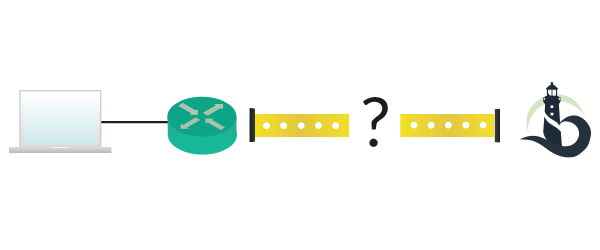
We now know the first device we connect to, but this is just one step, the easiest one. What’s behind your home network, the “real Internet” is still unknown. The truth is that, in the end, the concept is quite similar to your home network. Before we can go any further, you need to understand what a router is. We will have a lot of time to put a more technical definition in your mind, but for now this definition will be more than enough.
A router is an intermediary network device with the role of forwarding (route) data between other devices (even other routers), based on a “geographical” addressing scheme.
In other words, a router will receive some information from a device (such as your laptop) that is destined for another device (and not for the router itself). The router knows, based on the information received, where to send that piece of information. Maybe it send it to another router, that will repeat the process, and this goes on until we reach the destination. In theory, it is trivial, but it’s not. For example, what if the addressing scheme is not geographically consistent (some addresses you believe to be in the US are in Europe), which is a common case? What if a router has two path to reach the same destination? How we can prevent the piece of information from looping if it keeps getting back to the same router over and over? These are just some questions about “How the Internet works, exactly?” and they all have an answer, otherwise Internet wouldn’t be working right now.
A simple note before we continue, with geographical we do not strictly mean related to a geographical area. Instead, think that networks have their own geography, parallel to the real-world geography.
Now we know what the Internet looks like: a set of intermediary devices delivering the request from your laptop to the website and then the content from the website to your laptop. But wait for a second, what is the website? I mean, we translated the magic cloud into a set of routers, is it possible to translate the website in something tangible? Yes, it is! A website is nothing more than a service – an application – running on a computer. This computer will be considered a server since its main goal is to serve the requests of other computers. The website application will sit back and listen, waiting for a request. Each time a request is received, it will be analyzed and the related content will be sent back. A server can host many websites at the same time and while the application that listens to requests and provides responses is the same for most websites (two valid alternatives are Apache or Nginx), what actually change is the content provided in the response.
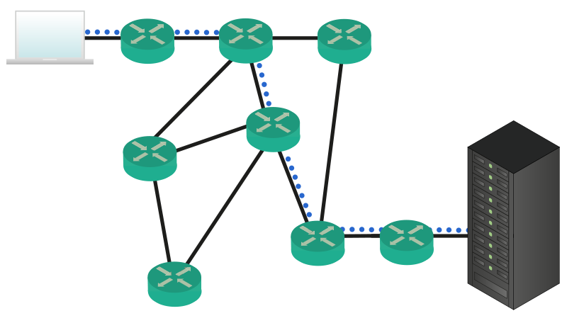
Another great thing to consider is that The Internet can survive everything. Earthquakes, major power outages, everything. This is because it is distributed in the world (routers making up the Internet are everywhere) and there isn’t a single point that all the Internet relies on. Of course, some devices are more important than others (your home router cannot compete with the devices that give connectivity to the whole Asia-Pacific region, for example), but these devices are redundant so that if one fails another one will take over its workload. But the magnitude of the Internet and its capillarity aren’t enough. Internet is Real-Time. With that, I mean two things. The first is the simpler to guess: you can get what you need instantly, in real-time. The second thing is not so obvious, but it’s much more important: the Internet can adapt automatically to changes and failures. If you think that devices within the Internet fail rarely, think again. At any given time there will be a device failed within the Internet. The good news is that other devices will recognize that and act consequently, moving the traffic onto another path. This is why the Internet is so powerful, and it can also be quite complex. To help simplify everything, the OSI stack has been developed.
Hiding the complexity with OSI
The title states it clearly: The OSI model has been designed to hide the complexity of networks. This is not completely true, but it is what it looks like. Before explaining what the OSI model is, let’s present the needs that made it necessary.
Take a look back at the previous picture, where your computer was communicating with a server somewhere in the Internet. We can see 5 routers directly involved in the process of forwarding data. Now, what is these routers were people? Imagine that the information is contained in a box, and these people pass that box between each other until it is delivered to the destination, like a supply chain. To select who will be the next person to pass the box to, there is a label on the box. That huge label contains an instruction for each person in the chain, written specifically for him. Once a person find the instructions, cross them with a marker and pass them to the next person, as learnt from the instructions. Now, Internet is worldwide, so not all the people in that chain will speak the same language. Therefore, each piece of instruction has to be written in a language that you are sure the intended receiver will be able to read. What if a person in the chain is replaced by another one who do not speak the same language? You have to rewrite the whole label and, most importantly, you – the first node – have to know all the possible languages. Isn’t that complex? In other words, you have to take care of everything and put a set of detailed instructions for everyone else. To make it even clearer, let’s list the major flaws of this approach.
- You have to know the path that your data will take beforehand
- You have to know every language in the Internet
- In case a node is replaced with another one who do not speak the same language after you sent your box, it will be lost because the new node won’t be able to forward it correctly
- If a node fails there are no alternative instructions to follow, so the box is lost
These are just a few, the easiest to understand for someone who is fairly new to networks. The OSI model addresses all of these problems, allowing enhanced scalability and performance. The OSI model is a set of protocols, but what is a protocol in a networking environment?
A protocol is a set of rules defining how the communication between two devices should happen.
Technically, a protocol is implemented with an algorithm (reasoning process on a device) and a set of messages exchanged between the two devices. The messages are the data exchanged between devices, whereas the algorithm is the application that will listen for that messages and that will understand them. Every communication happening over the Internet is defined by a protocol, and in the path between your computer and the website you will have to use several protocols. Fortunately, your computer and the network devices do all of that for you, this way you can just type the website URL (such as https://www.ictshore.com) and enjoy the view.
To hiding that complexity, thus resolving the problems listed above, we have to use protocols. Think of it this way: you have to send something and you put it into a box, but instead of applying a label defining all about how it should get delivered, you just write on the label the intended receiver. Then you close that box and you put into another box. On the outer box, you write the intended first receiver, then you send it to him. Once he receives it, he open the outer box and looks to the label of the inner box, then he thinks “Okay, to reach John I must give it to Mary!” and put your box in a newer outer box destined to Mary. This process continues until the box reach John. At this point, John open the box and read its content. This process is called encapsulation, and has a major benefit: you maintain reachability information about your target and you do not care about the path your box will take, intermediary devices will decide it for you. In other words, you create something that feels like a tunnel, a separate communication channel that goes through the Internet connecting your computer to the website, virtually directly.
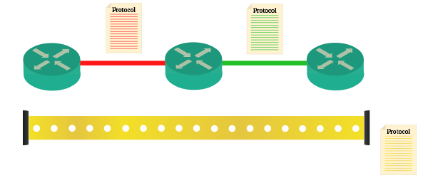
The picture above is a clear example of what encapsulation consists of. Protocols, represented by a set of rule (document), define how the communication should happen. A protocol defines the communication between the first and the second router, whereas another protocol defines the communication between second and third router. Yet another protocol defines how the communication should happen while passing over these routers. In other words, red and green protocols define how outer boxes should be made, while yellow protocol defines how the inner box should be made. The following image will make that even clearer for you.
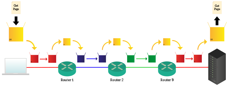
Your laptop knows that has to reach ICTShore, so it creates a request with “Get me the web page” and put it into a yellow box destined for ICTShore. Your laptop knows also that to get to anything in the Internet as to talk to Router 1, so it puts the yellow box into a red box destined for Router 1. Router 1 receives that box, open it and find out that the content is for ICTShore. He does not need to check the content of the yellow box because it knows that in order to reach ICTShore it has co contact Router 2. To talk with Router 2, however, he need to use another protocol, the blue protocol, so it put the yellow box into the blue box (the yellow box is always the same) and send it to Router 2. Then, Router 2 repeats the process and discover that the box has to be forwarded to Router 3, talking with the green protocol. It does just that and Router 3 understand that the box is for ICTShore, which is connected right there and deliver it to the server using the red protocol. The key fact is that neither your laptop nor ICTShore.com know what are the protocols used in the network, they only know the yellow protocol and the red protocol (because they both talk with their router using that protocol). Protocols in the path may change, but they do not have to know them. This makes everything more flexible, because if a protocol changes anywhere in the Internet just the connected nodes will know that. In the end, the server will open the request, read it and craft a response.
There are some very specific rules to define how protocols should interact with each other. For them, check out the following section.
Categorizing protocols
We already defined what a protocol is (just as a reminder, it is a set of rules defining how the communication between two devices should happen), but then we introduced encapsulation and the fact that protocols are put one into the other. This necessarily mean that protocols talks to each other at some level: based on the intended receiver, an intermediary device will select the next router to send the box to. So, it has to use the right protocol/encapsulation (outer box) to talk with that router. Protocols may start merging into each other if we do not have a way of categorizing them. Fortunately, this is exactly what the OSI model is about:
The OSI model (or OSI stack) is a way of categorizing protocols in layers based on their usage. Other two stacks used to categorize protocols are the TCP/IP model and the Hybrid model (that merges OSI with TCP/IP).
OSI stands for Open Systems Interconnection, because it has been designed by ISO (International Organization for Standards) to enhance the creation of protocols allowing machines of different vendors to talk with each other. Decades ago, systems from a vendor (such as IBM or Apple) were not able to talk with each other, because each of them used its own system of communication. Thankfully, now there is a standardized model that allow everyone to talk with everyone else.
To reach its goal of interconnecting multiple different systems, OSI defines seven different layers of protocols in a very precise and strict way. Information is passed only to contiguous layers (the protocol on the layer next on top or on bottom) and he cannot “jump” some layers. This way, if something changes in a layer, only the two connected layers will notice that change.
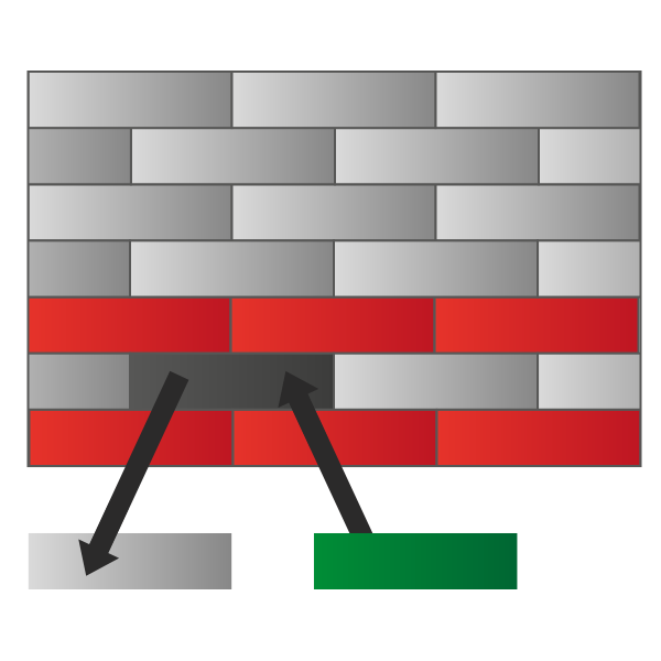
Not only a layer can talk only to its directly connected ones, but it also “controls” the layer being directly below. This is because if a router receives a box for a non-connected device, it has to find what the next router should be and, based on that, use the appropriate “outer box” (protocol) to communicate with that router. Maybe, with another next router, a different protocol would be needed. With that, we can understand that your application (your surfing the web) is in the top layers and the cable connecting two routers is at the very bottom of the OSI model. So, you start from the top when you send something and it is encapsulated each time your content goes through a layer. Finally, it is put on the cable and when it reaches the destination it is passed to upper layers until all outer boxes are removed. It may seem a little bit abstract at this time, but as soon as you understand the role of each layer everything will be clearer.
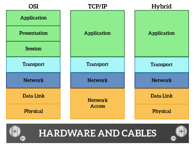
The protocols are always the same, these three models are just three different ways of categorizing them. As you can see, these three different stacks are quite similar. Let’s start from OSI, raising the stack from the bottom (starting from hardware and cables).
- Physical – this layer controls how data are put on the cable (frequencies, signals and all other stuffs that are more related to physics and electricity than ICT)
- Data Link – defines how much data can be put on the cable at the same time, how it should be formatted and also detects if something goes wrong during the transmission
- Network – defines addressing information for non-directly connected nodes, allowing you to reach a remote device
- Transport – defines addressing information for application and services, while the network layer allows you to reach a remote device the transport allow applications on remote devices to talk with each other
- Session – ensure that information is delivered correctly between remote applications (it may be handled by protocols at the transport layer without the need of a session-specific protocol
- Presentation – define information about how to compress and present your content, mostly used for real-time traffic such as voice or video streams
- Application – the data of your application, such as the request for a web page
So, your browser (application) creates a request that sounds a lot like “Get me that website page” and pass that to the presentation layer. It is just a web page, so nothing needs to be done here. The request is passed to the session layer, which in the case of web pages is handled by a protocol that works at transport and session layer at the same time: TCP. This protocol identifies your browser and the application “delivering website” (web server) on the remote device, then pass it to the network layer. The network layer identifies where the remote server is and then pass it to the data link layer, which then send the data to the next connected device in the path using the physical layer. Devices in the path inspect your traffic up to the network layer to identify where it should go. When it reaches to the destination, after the server understand that it received a request specifically for itself (layers 1 through 3), it deliver that content to the Transport layer that identify the local application that should respond to that request. All in all, this is how Internet works. Just to make that clearer, we have the following image that explains the path of your data.
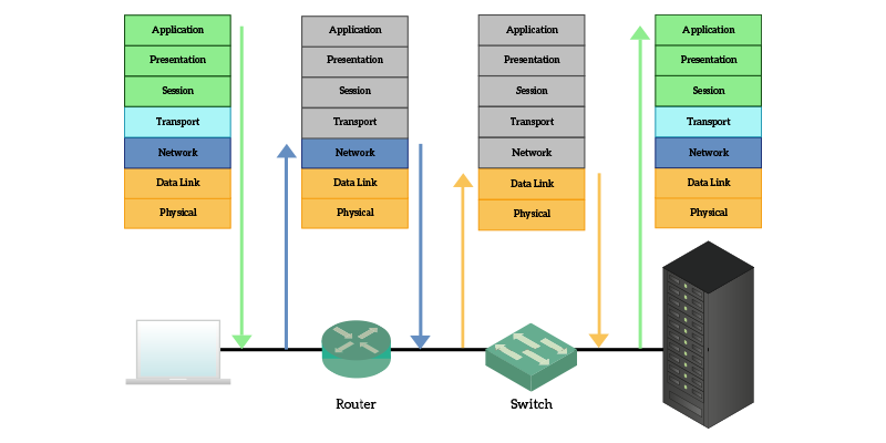
The user resides on top of the OSI model, because he is the one using and controlling applications. He is the one deciding that he wants to surf a given website. So, he is the one triggering the process by typing the URL and pressing enter. The request is processed and goes down to the physical layer, which transmits it onto a cable. When it reaches a router, he just have to check where the information has to go, it does not care about what the content could be, so it just open the Data Link box to inspect the Network layer and find out where the information has to go. Switches (other network devices), inspect only the data link layer instead. The only devices that will be reading the application layer are the sender and the receiver.
TCP/IP stack is just a way of looking at the network focusing on Network and Transport layer. It has been designed this way as an approach where you do not care how you put information on the cable, it is just “Network Access” and you not care about what are you putting on it is just “Application data”. What you do care about is how that data reach the intended application. Hybrid model is used as an approach when you do not care about what the application data are, but you do care about how you access the network.
In the next articles, we will approach each layer separately, with one or more articles per layer. Now, instead, we will have a brief section explaining each TCP/IP layer and its role in a little more detailed manner. For that, just read on.
Network Access layers
At the network access layer we find the physical layer and, on top of it, the data link layer. These two layers are called “Network access” from the TCP/IP stack because they bridge a more abstract and logical information, coming from upper layers, onto the physical stuff. They are the one granting the functionalities of hardware and allowing its use to upper layers.
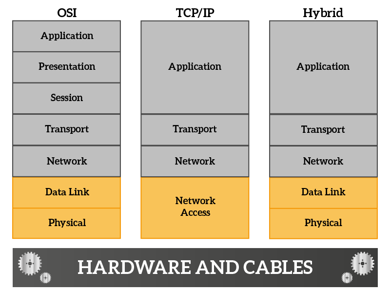
At the very bottom of the OSI stack, we have the physical layer, which takes information in form of bits and translates that information into electromagnetic signals (cables and wireless) or light pulses (fiber optic). This layer does not know anything about the information, does not know what the information is, why it is being sent and not even who is the intended receiver, all of this stuff are handled by the upper layer. The only thing we care about in this layer is to generate a signal that can travel over a given media and that can carry as much more information as possible. The fact that we do not know the receiver at this layer is because we trust the Data Link layer, if the Data Link layer decided to generate a signal on a cable instead than another, the physical layer just translate the information into signals, assuming that we have the right receiver on the other side.
From what we just said, we understand that the physical layer delivers information in a mindless way to directly connected devices. However, without knowing the information itself, it is not reliable and cannot find out if data gets corrupted during the transfer (maybe due to some interferences). We need another layer to control and enhance the physical layer: the Data Link layer. This layer controls the physical layer and it is divided into two sub-layers, named MAC (Media Access Control) and LLC (Logical Link Control). The MAC sub-layer interfaces directly with the physical layer, controlling the generation and reception of signals, while the LLC is the part that “faces” the Network Layer and receives orders from it. The Data Link layer provides the following features.
- Error detection, it can find out if the information gets corrupted after being transferred to a connected device – retransmission is not handled, the role of this layer is to find out if the information is valid and, if not, just discard it (not even notifying the sender)
- Local addressing information, it knows which cable to use in order to reach each directly connected device
These two features combined allow full control of the communication with directly connected devices. At this point, you might think that if the device/server/website you are trying to reach is directly connected you can just skip every other layer and put the request into the Data Link layer. Well, think again: the Application will never be informed whether the destination is directly connected or not, so all the layers are always traversed. More than that, this is the only way that the same process (Layer 7 through 1) can be used regardless of the position of the communicating devices within the Internet.
Network and Transport layers
On top of the Network Access, we have Network and Transport layers. Combined, they allow applications to talk with each other. In this section we will explain in a little more detailed manner what are their roles exactly.
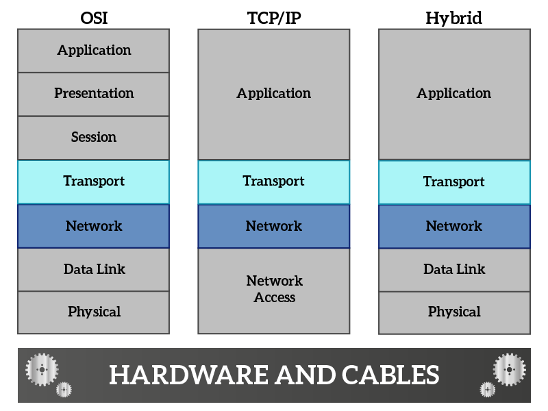
The Network layer controls directly the Data Link layer. It tells to that layer what directly-connected device send the information to, so that the Data Link layer can select the right cable to reach that device. This is possible because internet-wide addressing information is processed at this layer. The network provides direction to reach virtually any device in the Internet and deliver data to it. However, should the data get lost in the path (the Data Link layer discard a “box” because it has detected some interferences that have corrupted the data), the network layer is not notified and the data is lost. Re-transmission has to be handled by upper layers. This layer works a lot like a post office: it processes addresses, each address containing all the required information to reach the receiver. For each received box, we look at the country. If it is for another country, we send it to a post office into the other country, because we do not know how to (nor can) reach the specified address. The other post office will send the box to the right city, where the postman will deliver it to the receiver. This is exactly what the network layer does.
Once the box has reached the right building, the job of the postman is completed. Now it’s time for someone else to deliver all the boxes received in a building to the right person. This is the job of the transport layer, which takes data from the network layer and, with its own addressing system, deliver it to the right application. Addresses of applications are unique within the same computer, while network addresses are unique within the Internet (this is not completely true, but for now think it is). A combination of addresses from transport layer and network layer is called socket, and identifies a unique connection in the Internet.
The protocol used nowadays at the network Layer is the IP (Internet Protocol), while we use mainly two transport protocols: TCP (Transmission Control Protocol) and UDP (User Datagram Protocol).
Application Layer
The Application layer resides on top of all the stacks, with TCP/IP and Hybrid model including also Presentation and Session layers in it. This is due to the fact that often time presentation and session-related tasks are handled by the application itself. Just to be on the same page, an application is a web browser, a web server, an online game, an app on a smartphone showing you online content, and such.
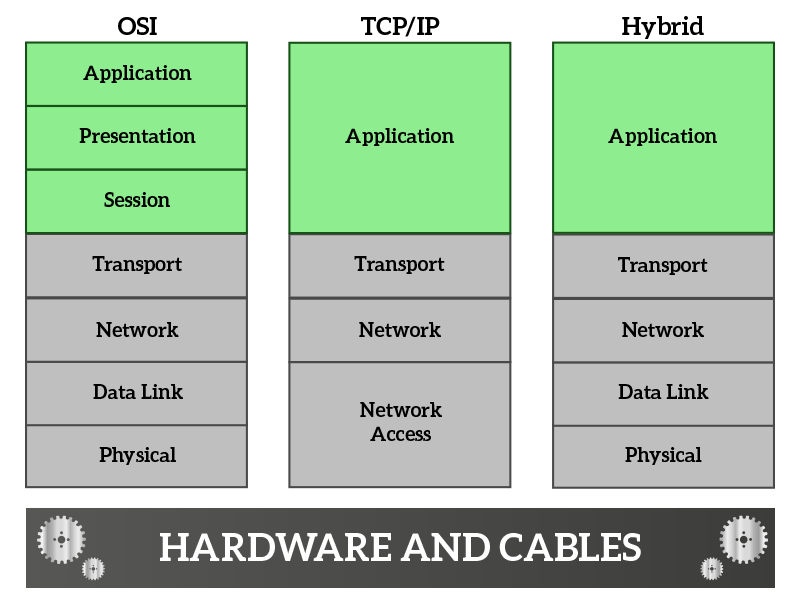
Coming from the Transport layer, the first layer we encounter is the Session layer. Its main job is to ensure that data reach the indented destination (application). In other words, it implements some mechanisms that allow the retransmission of the data in case something gets lost. In case we do not care to recover what gets lost, but we do want to know if something has been lost, this functionality is always handled at this layer. TCP is a transport protocol that handles retransmissions, therefore it works also at the session layer. UDP has no mechanism to recover data lost in the path (it is considered unreliable), so if we want to use UDP but we want to know if something gets lost we can use RTP (Real-Time Protocol) at the session layer. This protocol is commonly used for streaming traffic, because streaming is real-time in nature and it needs to be fast, we do not have time for retransmissions. These concepts will be explained in much more details in a dedicated article along the CCNA course.
The next layer we encounter is the Presentation layer, which is in charge of handling how data is presented to the application. It is rare to find protocols working only at this layer because it is implemented in the application itself most of the time. Of course, if it is implemented in the application layer, the programmers that developed the application presents the data to the application itself the way they want so that the application can process them easily. A case when we see the presentation layer as standalone is for VoIP traffic. For VoIP, before the call is made (established), a codec is negotiated. A codec is a way of compressing audio (and/or video) that influences the quality of the stream, the performance in terms of bandwidth (how much internet speed is required) and computational power (how much powerful your PC has to be to make you listen to that audio). Different codecs are used depending on the needs, some may need the best quality, others will have to sacrifice it due to limits in internet speed.
Finally, we have the application layer. We cannot say anything specific about this layer, simply because each application is different and defines its own protocol(s). However, many applications are standard, such as the web, which is nothing more than HTTP (Hyper-Text Transport Protocol) traffic. HTTP is the protocol used to surf web pages, you type URLs starting with http://. Another protocol is HTTPS, which is the secure version of HTTP: data can be read-only from the sender and receiver. There are tons of protocols working at this layer, such as SMTP, POP3, and IMAP for emails. We can list tons of different protocols, but this is out of the scope for this article.
Okay, this article was full of new concepts, so feel free to take some time to truly understand them. What we learnt will be a solid ground to build powerful networking skills. It may seem a bit complex if you are completely new to networking, but the more you go deep, the more everything gets clearer. You might have guessed, the next articles in the series (CCNA course) will face each individual layer of the OSI stack in a very detailed manner. Before doing that, we will encounter yet another article to explain binary math, the foundation of ICT.
