You know that switches can work without any configuration. Nevertheless, you know you can configure switches for remote management and tune some settings (like the banner). However, we haven’t talked just yet about the ways we can alter the way a switch works. In this article, we cover the VLANs configuration on a Cisco switch. We will learn how to segment a switch into multiple broadcast domains and how to extend the same broadcast domain to multiple switches.
As any hands-on article, this guide leverages a lab where you can practice what you learn. Use the link below to download it for free the Cisco Packet Tracer lab.
Once you downloaded the lab, open it with Cisco Packet Tracer. Then, work on it while reading the instructions you find in this post.
VLANs Configuration Lab Intro
The topology
The following picture shows all devices used in that lab, as well as the connections between them.
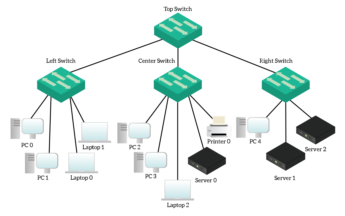
Don’t be scared by this huge topology, it simpler than you might think. At the very top, we have a device called “TopSwitch” that interconnects three other switches: left, center, and right. Each of these peripheral switches connects end-devices. We have four different type of devices: desktop computers, laptops, servers, and printers. For this lab, we are going to configure the switches only. However, we will use the end devices to perform some connectivity tests.
The Requirements
As in the title, we are going to do the VLANs configuration for all the switches in the topology. This includes the creation of the VLANs, the access ports settings, and the trunk configuration. Before disclosing parts of the configuration, we will present the theory behind (such as the 802.1q protocol). The following table presents the VLANs configuration we aim to achieve.
| ID | Name | Subnet | Port range on peripheral devices |
|---|---|---|---|
| 99 | Black-Hole | None | None |
| 101 | Desktop-PCs | 10.100.1.0/24 | FastEthernet0/1 to FastEthernet0/9 |
| 102 | Laptop-PCs | 10.100.2.0/24 | FastEthernet0710 to FastEthernet0/19 |
| 201 | Servers | 10.200.0.0/25 | FastEthernet0/20 to FastEthernet0/22 |
| 301 | Printers | 10.105.0.0/24 | FastEthernet0/23, and FastEthernet0/24 |
List of Steps
To meet the requirements of this lab, we are going through several steps. Here’s a quick list to help you skim the article.
- Introduction to VLANs and trunks (here we have the theory)
- Creation of VLANs (for all switches)
- Configuration of access ports on peripheral switches
- Setting up trunk ports on peripheral switches
- Configuration of trunk ports on the TopSwitch
- Connectivity tests
It is time to start!
Some Theory about VLANs and Trunks
What are VLANs?
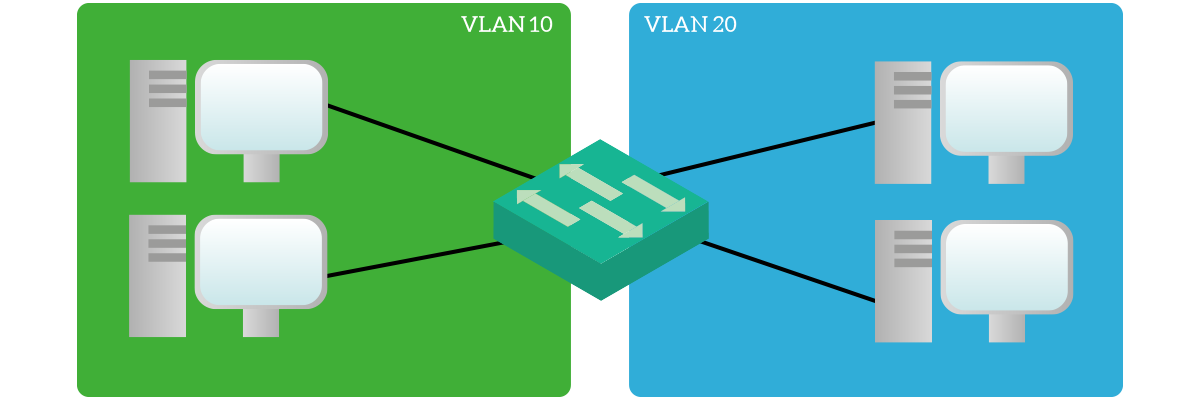
VLAN stands for Virtual Local Area Network, and it is a technology to divide your network into segments. Specifically, each VLAN is an independent broadcast domain. As a result, two devices in two different VLANs need a router to talk between one another, as they cannot do it directly. Provided that, the powerful thing about VLANs is that they are under complete control of the administrator. In other words, you are able to create or delete VLANs at will. However, VLANs alone are useless: you need to assign them to ports. You can configure the switch to have some ports in a VLAN and some ports in another. Consequently, devices connected to ports in the same VLANs can talk directly, while inter-VLAN communication requires a router.
The details
You can identify VLANs by their VLAN ID, a number ranging from 1 to 4094. This means that you will be able to use up to 4094 VLANs on a switch. However, VLANs after 1005 are part of the “extended range” and we won’t use them, at least for this article. Instead, we will use the normal range, VLANs from 1 to 1005 (note that VLAN 0 is not available). By default, a switch has 5 VLANs: 1, 1002, 1003, 1004, 1005. VLANs 1002-1005 are used to emulate a token ring, a legacy feature. You cannot remove nor edit them, and you will (almost) never need them. Instead, VLAN 1 is the default VLAN: all the ports of a switch are in that VLAN by default.
You can also configure the same VLANs on multiple switches, connect them together, and have the same VLAN to propagate on multiple switches. To do that, you need to be sure that the port of a switch used to connect to another switch has the same VLAN on both switches. This way, you will propagate that VLAN.
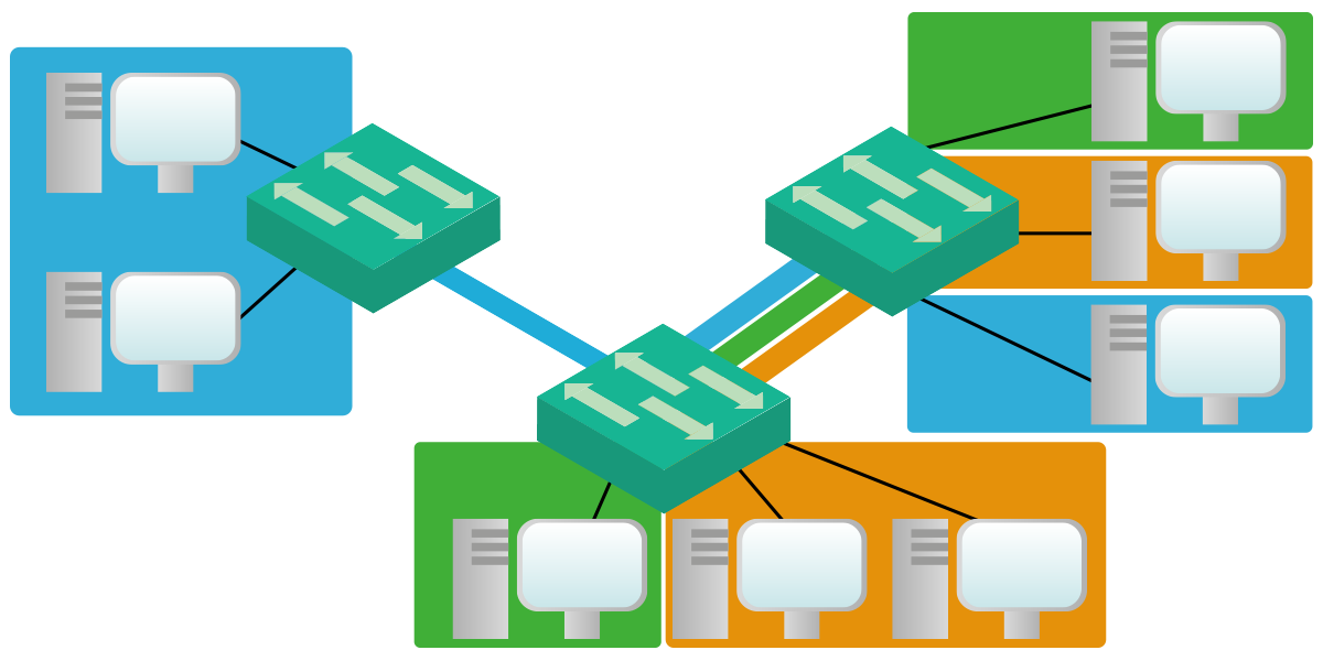
However, we have a better way to propagate VLANs between switches: trunks.
What is a trunk?
When talking about VLAN, a trunk is a link (a port) that carries traffic for multiple VLANs. You can configure a port in two ways, as an access port or a trunk port. Each access port will forward traffic for a single VLAN using Ethernet frames. Instead, a trunk port will forward traffic for multiple VLANs (even all). While a device connected to an access port does not need to know about VLANs, a device connected to a trunk port needs to know about them. This is because we need to send some information to distinguish between VLANs over a trunk, and both devices need to understand it. However, for this purpose, the Ethernet protocol is not suitable.
On trunk links, we can use either Inter-Switch Link (ISL) protocol or IEEE 802.1q. ISL is a Cisco proprietary yet a legacy solution, while 802.1q (or dot1q) is a standard technology. Since dot1q happens to be also the most efficient one, this is the one to go for. Moreover, most switches will support this one only. A dot1q frame is very simple: it is an ethernet frame with the VLAN ID squeezed in. In the frame, the VLAN ID is called tag.
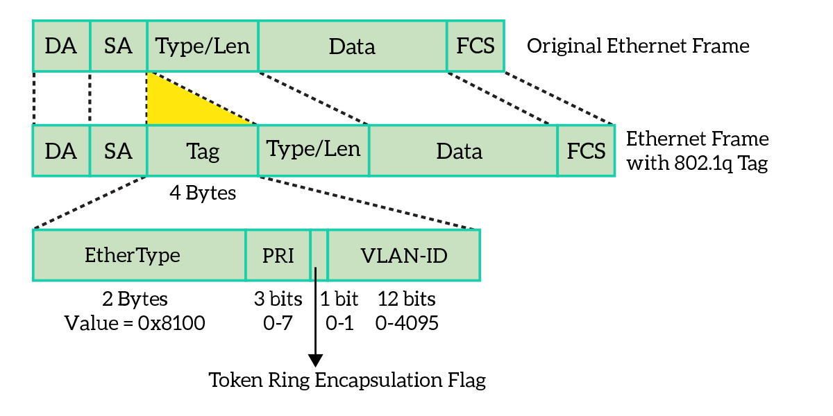
This way, the device on the other side checks the VLAN ID in the frame and know on which VLAN to send this frame. Remember that trunks are used to span multiple VLANs between switches, but they maintain the isolation between VLANs.
Some considerations on trunks and access ports
End-devices generally do not talk with 802.1q, but only with Ethernet. They have no conception of VLANs, thus they are not even aware of being on a VLAN instead of another. When a switch receives a frame on an access port, the first thing it does is the lookup in the MAC address table. This way the switch determines the exit interface (or interfaces). If the exit interface is an access port, then the Ethernet frame is sent with no alteration. Instead, if the exit interface is a trunk port, the frame is tagged with the VLAN ID of the originating access port.

Obviously, the same concept applies also for frames from trunk ports to access ports. This time, frame is un-tagged the original Ethernet frame. This is completely transparent to end-devices: you cannot find out how many switches separates you from your target device.
Before starting, we need to make another consideration on trunks. We are talking about the native VLAN. This is a setting of the port to identify the VLAN of untagged frames. In other words, it is possible that you receive a standard ethernet frame on a trunk port. When this happens, the switch will consider it part of the native VLAN. By default, VLAN 1 is the native VLAN on all trunks. This was originally designed to migrate from networks with hubs, allowing interoperability. However, in modern networks, we expect only tagged frames.
Step-by-step VLANs Configuration
Creating VLANs
For a Switch VLANs Configuration, the first thing we must do is creating the VLANs. VLANs configuration must be consistent between all switches you want to propagate the VLANs onto. In this lab, we have four switches and we want all of them to work with the same VLANs. Therefore, we will have to replicate the configuration on all four switches.
To create a VLAN, we use the vlan command followed by the VLAN ID we want to use. This will create the VLAN if it doesn’t exist already, and put us in the VLAN configuration prompt. From there, we can set a description to clarify the purpose of this VLAN (using the name command). Here is what we have to type.
Switch(config)#
Switch(config)#vlan 99
Switch(config-vlan)#name Black-Hole
Switch(config-vlan)#exit
Switch(config)#vlan 101
Switch(config-vlan)#name Desktop-PCs
Switch(config-vlan)#exit
Switch(config)#
Switch(config)#vlan 102
Switch(config-vlan)#name Laptop-PCs
Switch(config-vlan)#exit
Switch(config)#
Switch(config)#vlan 201
Switch(config-vlan)#name Servers
Switch(config-vlan)#exit
Switch(config)#
Switch(config)#vlan 301
Switch(config-vlan)#name Printers
Switch(config-vlan)#exit
Switch(config)#
We created a VLAN with the ID set to 101, set the name to “Desktop-PCs” and then we repeated the process for VLANs 101, 102, 201, and 301. Note that you don’t need to type the exit command each time. Now we can see them in the show vlan brief command output.
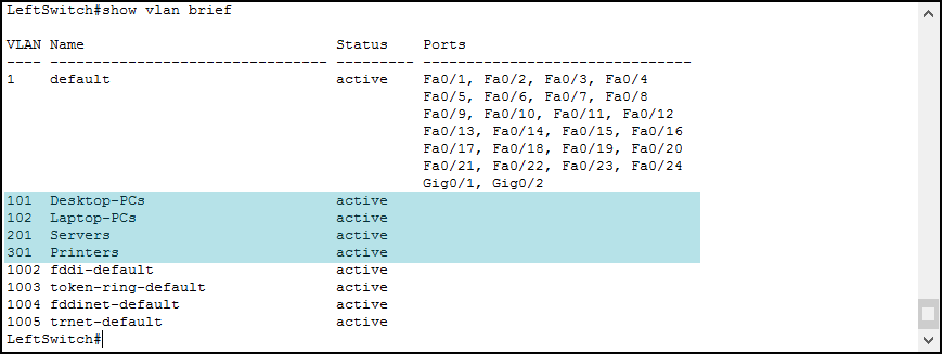
Note: We will explain the purpose of the “Black-Hole” VLAN later on when talking about trunks.
The output of this command is very straightforward. It shows you a table with four columns, the VLAN ID, the VLAN name, the status, and the list of access ports in that VLAN. Note that in this list of ports you will find access ports only, not trunks.
Our newly created VLANs have no access ports associated. We need to associate ports manually, and we will do that in the next section. However, before we do it, ensure you create the VLANs on all switches.
Configuring access ports
Now, we need to tell each port which VLAN it belongs to. We do it under the interface configuration prompt that we can reach through the interface command. However, we need to do the exact same configuration on multiple ports. In this case, we can use the interface range command. With this command, you still enter the interface (technically interface-range) prompt, but what you type is applied to multiple interfaces. Here are two examples.
interface FastEthernet 0/9enters the interface configuration prompt and applies everything FastEthernet 0/9 interface onlyinterface range FastEthernet 0/12, FastEthernet 0/15 - 17enters the interface-range configuration prompt and applies everything you type to interfaces FastEthernet 0/12, 0/15, 0/16 and 0/17
No matter which method you choose, we need to do two things. First, using switchport mode access command we hardcode the interfaces to be access ports. After that, we use switchport access vlan, followed by VLAN ID, to specify to which VLAN the port belongs. If you remember the initial requirement table, all the peripheral switches have the same port configuration. Here is what we need to type to do the configuration described in the requirements.
Switch(config)#
Switch(config)#interface range fa0/1 - 9
Switch(config-if-range)#switchport mode access
Switch(config-if-range)#switchport access vlan 101
Switch(config-if-range)#exit
Switch(config)#
Switch(config)#interface range fa0/10 - 19
Switch(config-if-range)#switchport mode access
Switch(config-if-range)#switchport access vlan 102
Switch(config-if-range)#exit
Switch(config)#
Switch(config)#
Switch(config)#interface range fa0/20 - 22
Switch(config-if-range)#switchport mode access
Switch(config-if-range)#switchport access vlan 201
Switch(config-if-range)#exit
Switch(config)#
Switch(config)#interface range fa0/23 - 24
Switch(config-if-range)#switchport mode access
Switch(config-if-range)#switchport access vlan 301
Switch(config-if-range)#exit
Switch(config)#
As a tip, the exit command is not needed for the sake of the configuration. We are using it here just to give you a clearer idea of what we are configuring. Repeat this step of the VLANs Configuration on LeftSwitch, CenterSwitch, and RightSwitch. After that, we will be able to see these changes in the show vlan brief command output.
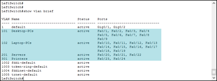
Configuring trunks – the commands
Since we have completed all the VLANs configuration on each switch, we only need to propagate these VLANs consistently. All peripheral switches connect to TopSwitch using their GigabitEthernet 0/1 port. However, this port is currently in VLAN 1 so the VLANs configuration is not consistent. This is because data from any VLAN different than 1 cannot pass from a switch to the other, so VLAN 101 on LeftSwitch is not part of the same broadcast domain of VLAN 101 on TopSwitch. Therefore, we need to setup trunks.
You can do all the configuration of a trunk in the interface configuration prompt. Hence, we are going to enter it with the interface command. At this point, we need to type in several commands. First, we force the interface to be a trunk using switchport mode trunk command. Basically, this is all you need to type if you want your trunk to work. A trunk created this way will carry all VLANs and use VLAN 1 as native.
In spite of simplicity, we are going to add three more commands to increase security. Cisco switches can detect when they are connected to one another and form a trunk automatically. This is because of the Dynamic Trunking Protocol (DTP), a Cisco technology. Even if this makes things easier, we don’t want that. Anyone could use this protocol to try to form a trunk with our switch or to grab sensitive information. Therefore, we disable it using switchport nonegotiate. In this lab, we are going to do it for trunks only, but you should do it for all ports in real-life. Note that this command is available only if you previously forced the port to be either trunk or access.
Remember when we created the Black-Hole VLAN? We are going to use it there as the native VLAN for our trunks. This will help us to prevent VLAN-hopping attacks, where a hacker could reach another VLAN leveraging the native on trunks. Therefore, we have created a VLAN containing no access port. This way, when we assign it as native to the trunk with switchport trunk native vlan command, we are practically disabling the native VLAN. So, if someone is able to step in and insert untagged traffic into the trunk, the switch will drop it because it will be received on VLAN 99.
As said earlier, our trunks will carry all active VLANs, up to 4094. Instead, we want it to carry only the VLANs we created. We set that using switchport trunk allowed vlan followed by a list of VLANs. Since this commands refers only to VLANs that actually get tagged, you don’t need to include the native VLAN. You can use this command with several keywords:
switchport trunk allowed vlanfollowed by a list, this list of VLANs will override the previous oneswitchport trunk allowed vlan addfollowed by a VLAN ID, that VLAN will be added to the already-existing listswitchport trunk allowed vlan noneremoves all the VLANs, effectively blocking the trunkswitchport trunk allowed vlan removefollowed by a VLAN ID, that VLAN will be removed from the already-existing listswitchport trunk allowed vlan exceptfollowed by a VLAN ID, override current settings with all VLANs but the one specified
Configuring trunks on peripheral switches
Now that we already know the commands to type, we can go pretty fast on this step. Provided that the port to make the trunk is the GigabitEthernet 0/1, here’s what we need to type.
Switch(config)#
Switch(config)#interface GigabitEthernet 0/1
Switch(config-if)#switchport mode trunk
Switch(config-if)#switchport nonegotiate
Switch(config-if)#switchport trunk native vlan 99
Switch(config-if)#switchport trunk allowed vlan 101-102,201,301
Switch(config-if)#exit
Switch(config)#
Do this for all peripheral switches (LeftSwitch, CenterSwitch, and RightSwitch). To verify that your trunk configuration is correct, issue the show interfaces trunk privileged exec command.
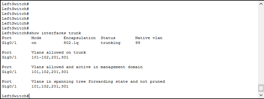
The show interfaces trunk command presents you the list of trunks on your switch four times, each time showing different pieces of information.
- In the first table, you see the mode (on means that the trunk is hardcoded with
switchport mode trunk), the encapsulation protocol, the status, and the native VLAN - Below that, you see the allowed VLANs for each trunk you defined with
switchport trunk allowed vlanscommand - Then, right below, you see the list of allowed VLANs currently active
- Finally, you see the VLANs that are effectively passing on the trunk (we will talk about pruning later)
Remember: Always check the last table if you are looking for the VLANs effectively in use on the trunk!
Configuring trunks on “TopSwitch”
For the last part of this VLANs Configuration, we are going to configure trunks on TopSwitch. This device acts as a central point because all communication between other switches must flow through this. TopSwitch is connected with LeftSwitch on FastEthernet 0/1, with CenterSwitch on FastEthernet 0/2 and with RightSwitch on FastEthernet 0/3. Moreover, the configuration commands are the same from the peripheral switches – and the same for all three interfaces. As a result, we can use the interface range command to speed things up.
Switch(config)#
Switch(config)#interface range FastEthernet 0/1 - 3
Switch(config-if-range)#switchport mode trunk
Switch(config-if-range)#switchport nonegotiate
Switch(config-if-range)#switchport trunk native vlan 99
Switch(config-if-range)#switchport trunk allowed vlan 101-102,201,301
Switch(config-if-range)#exit
Switch(config)#
All done! Your score on the Packet Tracer activity should be 100% by now. If not, try to review the commands we used and try the “Check Results” button to see what you missed.
Connectivity Tests
The purpose of VLANs configuration is to divide end-points into subnets logically. Since the same VLAN can span multiple switches, you don’t have to group devices by physical locations, you can group them by logical function. Moreover, with a VLANs Configuration, you can force inter-VLAN traffic to pass through a central device, where you can apply policies and restrictions (who can access what). Since we don’t have that device just yet, in this lab inter-VLAN traffic will be dropped.
To test that, just try a few pings from PCs, laptops, or servers. The complete addressing scheme is reported below.
| Device | IP Address/CIDR |
|---|---|
| PC0 | 10.100.1.0/24 |
| PC1 | 10.100.1.11/24 |
| PC2 | 10.100.1.12/24 |
| PC3 | 10.100.1.13/24 |
| PC4 | 10.100.1.14/24 |
| Laptop0 | 10.100.2.10/24 |
| Laptop1 | 10.100.2.11/24 |
| Laptop2 | 10.100.2.12/24 |
| Server0 | 10.200.0.10/25 |
| Server1 | 10.200.0.11/25 |
| Server2 | 10.200.0.12/25 |
| Printer0 | 10.105.0.10/24 |
By design, you will be able to ping only devices of the same type. PCs will ping only PCs, laptops will ping only laptops and servers will ping only servers. Note that applying this addressing scheme without a VLANs Configuration would have had the same result. However, traffic would have got mixed in the switches, having lower performance, and being more vulnerable to attack. The golden rule is this: always map a single subnet on a single VLAN and vice versa.
Conclusion
In this article, we learned how VLANs work and how switches talk using trunks. After disclosing the theory about those concepts, we immediately moved to the configuration parts. Here is a recap of the configuration commands we have seen.
vlanto create a new VLAN – thennameto give a name to a VLAN(in VLAN configuration prompt)interface rangeto configure multiple interfaces in bulk – thenswitchport modeto set the mode of the port (either access or trunk)- when the port is in access mode –
switchport access vlanto specify the access VLAN - when the port is in trunk mode –
switchport trunk native vlanto set the native VLAN - when the port is in trunk mode –
switchport trunk allowed vlanto specify the allowed VLANs - in any port mode –
switchport nonegotiateto turn off Dynamic Trunking Protocol (DTP)
Instead, the show commands are the following.
show vlan briefto verify the configuration of VLANs and access portsshow interfaces trunkto view quick information about trunk interfaces
With this knowledge about VLANs configuration, you are ready to move to switch troubleshooting. But let’s keep the next article in the CCNA course.


